
Seal assembly for counter rotating turbine assembly

a technology of assembly and turbine, applied in the direction of machines/engines, efficient propulsion technologies, liquid fuel engines, etc., can solve the problems of reducing turbine performance and efficiency, obviating the effect of efficiencies created, and increasing the efficiency of labyrinth seals at rotating outer drum interfaces

Active Publication Date: 2019-10-29
GENERAL ELECTRIC CO
View PDF14 Cites 10 Cited by
  • Summary
  • Abstract
  • Description
  • Claims
  • Application Information

AI Technical Summary

Benefits of technology

This patent describes a new invention and its benefits. The technical effects of the invention will be described in part in the description or can be inferred from the text. These effects can be useful for R&D personnel who are working on the invention.

Problems solved by technology

For example, labyrinth seals generally have leakage rates per unit diameter rise as diameter is increased, thereby rendering labyrinth seals increasing inefficient at rotating outer drum to static case interfaces.
As such, known labyrinth seal assemblies may result in leakages that may obviate efficiencies created by interdigitated turbine sections.
However, as the engine operates and rubs the static structure, over time the effectiveness of the seal assembly degrades, thereby reducing turbine performance and efficiency that may obviate the efficiencies of an interdigitated turbine section.

Method used


Image

  • Seal assembly for counter rotating turbine assembly
  • Seal assembly for counter rotating turbine assembly
  • Seal assembly for counter rotating turbine assembly

Examples


Embodiment Construction

[0039]Reference now will be made in detail to embodiments of the invention, one or more examples of which are illustrated in the drawings. Each example is provided by way of explanation of the invention, not limitation of the invention. In fact, it will be apparent to those skilled in the art that various modifications and variations can be made in the present invention without departing from the scope or spirit of the invention. For instance, features illustrated or described as part of one embodiment can be used with another embodiment to yield a still further embodiment. Thus, it is intended that the present invention covers such modifications and variations as come within the scope of the appended claims and their equivalents.

[0040]As used herein, the terms “first”, “second”, and “third” may be used interchangeably to distinguish one component from another and are not intended to signify location or importance of the individual components.

[0041]The terms “upstream” and “downstre...


PUM


Abstract

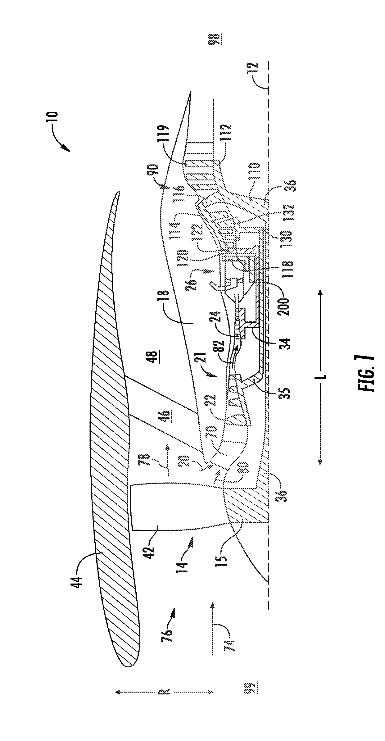
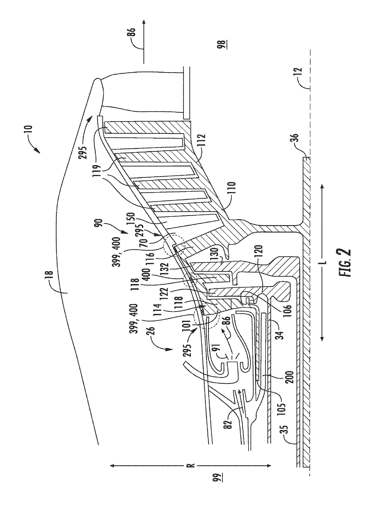
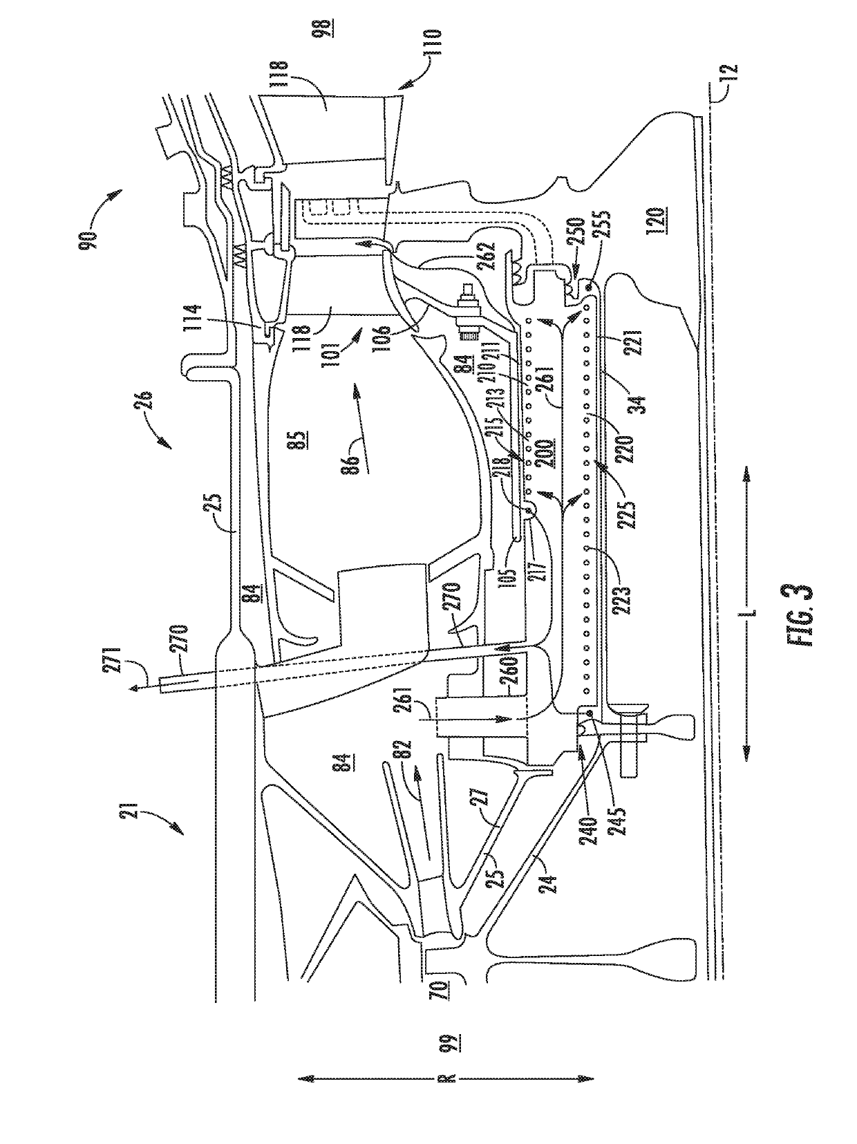
The present disclosure is directed to a gas turbine engine including a turbine rotor, a turbine frame at least partially surrounding the turbine rotor, and an outer diameter seal assembly. The turbine rotor includes an inner shroud, an outer shroud, and at least one connecting airfoil coupling the inner shroud and the outer shroud. The outer shroud includes a plurality of outer shroud airfoils extended inward along a radial direction. The outer diameter seal assembly includes a sliding portion disposed between the turbine frame and the outer shroud of the turbine rotor. The outer diameter seal assembly defines a secondary tooth at the outer shroud radially inward of a longitudinal face of the sliding portion, and a primary tooth defined axially adjacent to a radial face of the sliding portion.

Description

FIELD[0001]The present subject matter relates generally to gas turbine engine architecture and operation. More particularly, the present subject matter relates to methods of sealing and clearance control for turbine sections.BACKGROUND[0002]Gas turbine engines generally include a turbine section downstream of a combustion section that is rotatable with a compressor section to rotate and operate the gas turbine engine to generate power, such as propulsive thrust. General gas turbine engine design criteria often include conflicting criteria that must be balanced or compromised, including increasing fuel efficiency, operational efficiency, and / or power output while maintaining or reducing weight, part count, and / or packaging (i.e. axial and / or radial dimensions of the engine).[0003]Known conventional and interdigitated gas turbine engines generally include labyrinth seals between rotating and static members of a turbine section. Air generally needs to be sealed within cavities to avoid...

Claims


Application Information

Patent Timeline
Patent Type & Authority Patents(United States)
IPC IPC(8): F01D11/06F01D5/22F02K3/072F02C3/067F01D11/16F01D25/24F01D1/26F01D11/14F01D11/02F01D5/03F04D27/00F04D29/54
CPCF01D11/025F01D25/24F01D5/03F01D11/14F01D5/225F01D11/16F02C3/067F01D1/26F01D11/06F02K3/072F05D2240/24F05D2240/55F05D2260/52F04D29/545F05D2220/32F04D27/009F01D11/10Y02T50/60
Inventor GIBSON, NATHAN EVAN MCCURDYZATORSKI, DAREK TOMASZ
Owner GENERAL ELECTRIC CO
Learn More