
Crimp sleeve

a sleeve and crimping technology, applied in the direction of mechanical equipment, belts/chains/gearrings, and permanent deformation-induced connections, etc., can solve the problems of high coefficient of friction, small application size, and high degree of precision

Active Publication Date: 2019-11-05
THE NAT TELEPHONE SUPPLY
View PDF25 Cites 0 Cited by
  • Summary
  • Abstract
  • Description
  • Claims
  • Application Information

AI Technical Summary

Benefits of technology

This patent relates to ways to make strong end stops on cables and wires. The end stops are made using a process called axial pressing, which involves creating a tightly closed end on the wire or cable. This process results in a highly efficient use of material, with very little waste. The technique also eliminates any flash or parting flash, which is the small remaining material after the crimping process. Additionally, the patent suggests that adding control grooves in the outer diameter of the end stop sleeve can further reduce flash.

Problems solved by technology

The sizes of the applications are very small and exacting.
This method is process sensitive especially with inert materials such as stainless steel and Nitinol.
There is also a need to provide crimp sleeve material which has a high coefficient of friction since the gripping surface area of the sleeve is limited by usable space in the enclosure.
There is no existing method for doing this.
However, this does not have good process repeatability.

Method used


Image

  • Crimp sleeve
  • Crimp sleeve
  • Crimp sleeve

Examples


Embodiment Construction

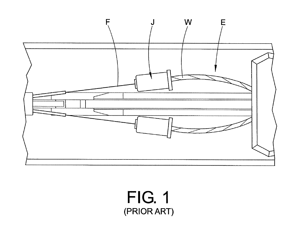
[0044]The present disclosure relates to splice and end stop sleeves. The sleeves are described in detail below.

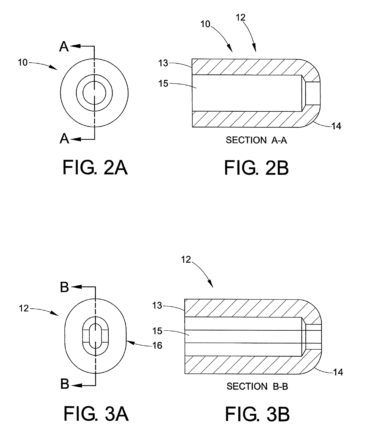
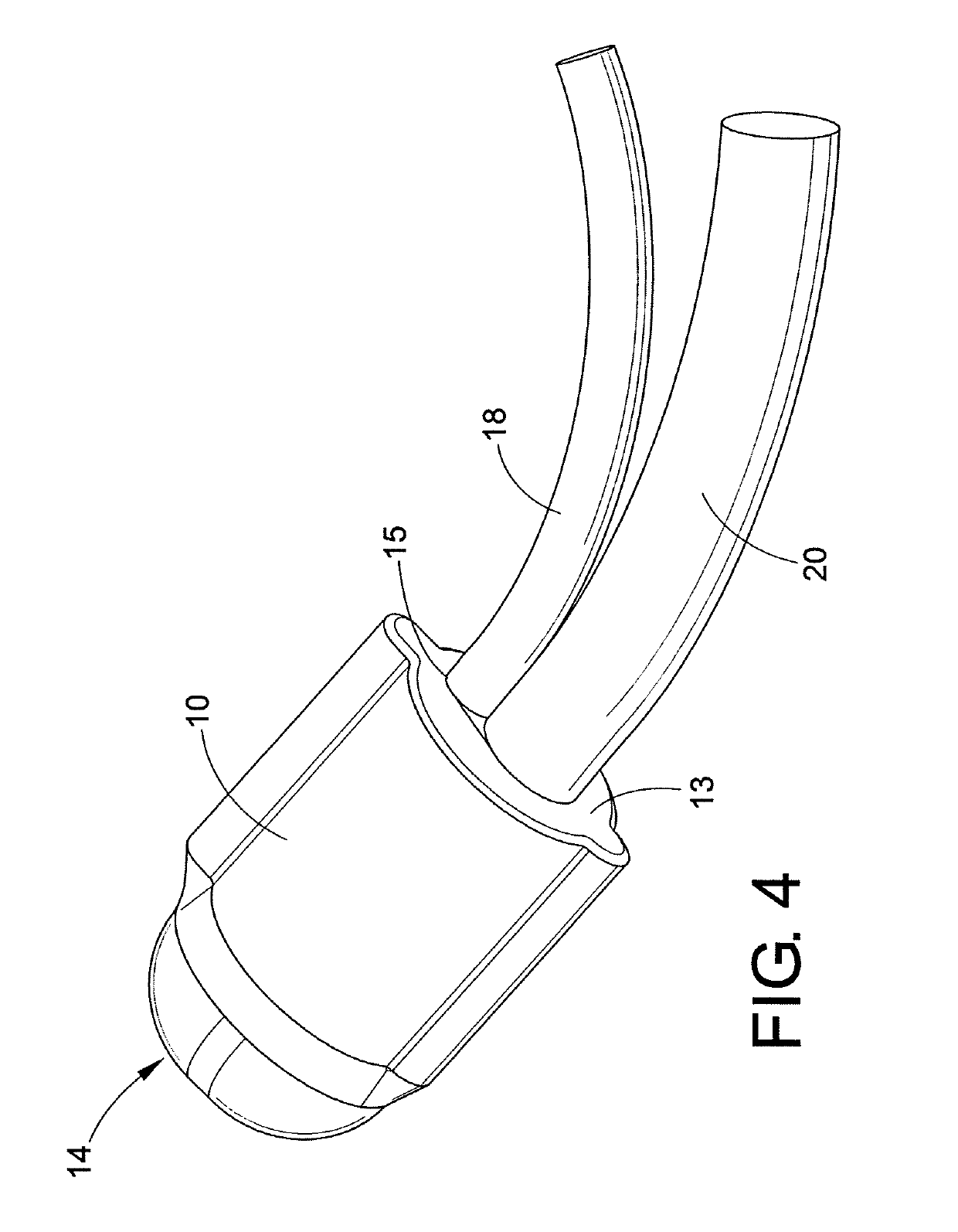
[0045]More particularly, referring to FIGS. 2A and 2B, a crimp splice sleeve 10 is made from titanium in accordance with a preferred embodiment of the disclosure. The sleeve is made using a tube 12 machined with a first end 13 having an opening 15 and a bullet nose closed end 14.

[0046]Referring to FIGS. 3A and 3B, the tube 12 may or may not be slightly flattened into an oval shaped cross section 16. Given the finish size constraint, an oval shaped cross section may be also necessary to allow insertion of both wires into the sleeve in as small a cavity volume as possible. Machining a sleeve 10 with a bullet nose end 14 eliminates the need for adding the bullet nose in a secondary operation.

[0047]The resulting compression ratio of the crimp is in the range of about 1.25 to 1.10. The compression formula is as follows:

(((volume of wire)+(volume of crimp sleeve)) / (volume of die ...


PUM


Abstract

A crimp sleeve assembly includes a body made from titanium and has a first open end and a second closed end. The crimp sleeve crimps a Nitinol wire and a PTFE coated stainless steel wire. An axial end stop sleeve assembly has a sleeve crimped by an axial die assembly which forms a tip of the sleeve into a closed end bullet and / or tapered nose wherein the sleeve is crimped onto an end of a wire rope such that the wire rope does not protrude from the closed end bullet and / or tapered nose and wherein the axial die assembly minimizes flash during crimping.

Description

CLAIM OF PRIORITY[0001]This application claims priority from U.S. Provisional Patent Application Ser. No. 62 / 084,731, filed on Nov. 26, 2014, the entirety of which is hereby incorporated by reference herein.BACKGROUND OF THE DISCLOSURE[0002]This disclosure relates to crimping sleeves. More particularly, it relates to a crimping sleeve for use in small areas such as used in commercial or industrial applications. Referring to FIG. 1, an existing enclosure or tube has a small envelope E within it in which the crimp sleeve at joint J must be used to join wire W to fiber F. The small envelope must accommodate both the crimp sleeve length and the crimp sleeve travel based on pull wire travel along a longitudinal direction.[0003]End stops for cables and wire are used throughout a multitude of industries. One of the current methods uses a standard crimp sleeve with tooling that swages material between two dies transverse to the wire.[0004]Another method uses a knot alone or a knot with a sl...

Claims


Application Information

Patent Timeline
IPC IPC(8): F16G11/02H01R4/20
CPCH01R4/20F16G11/025
Inventor DISANTIS, RAYMOND
Owner THE NAT TELEPHONE SUPPLY
Features
  • Generate Ideas
  • Intellectual Property
  • Life Sciences
  • Materials
  • Tech Scout
  • Unparalleled Data Quality
  • Higher Quality Content
  • 60% Fewer Hallucinations
Learn More