Brake control apparatus for vehicle

a technology for controlling apparatus and brakes, applied in the direction of automatic initiation, braking system, transportation and packaging, etc., can solve problems such as degrading safety, and achieve the effect of improving safety, increasing the period of opportunity and executing vehicle stability control

Active Publication Date: 2019-11-26
TOYOTA JIDOSHA KK
View PDF31 Cites 2 Cited by
  • Summary
  • Abstract
  • Description
  • Claims
  • Application Information

AI Technical Summary

Benefits of technology

[0006]The present disclosure provides a technique of allowing execution of vehicle stability control even when the vehicle stability control using a brake actuator is unavailable.
[0029]According to the above aspect, even when the pump provided in the brake actuator cannot be used, the vehicle stability control can be executed in the pseudo mode. Accordingly, compared to the related art, the opportunity and the period to execute the vehicle stability control are increased, and the safety is improved.

Problems solved by technology

When the vehicle stability control is not executed due to unavailability of the vehicle stability control using the brake actuator, safety may be degraded.

Method used


Image

  • Brake control apparatus for vehicle
  • Brake control apparatus for vehicle
  • Brake control apparatus for vehicle

Examples


first example

5-1. First Example

[0121]In a first example, the vehicle stability control for canceling oversteer will be described. In step S10 in FIG. 7, the brake ECU 51 determines whether a turning state of the vehicle 1 is the oversteer.

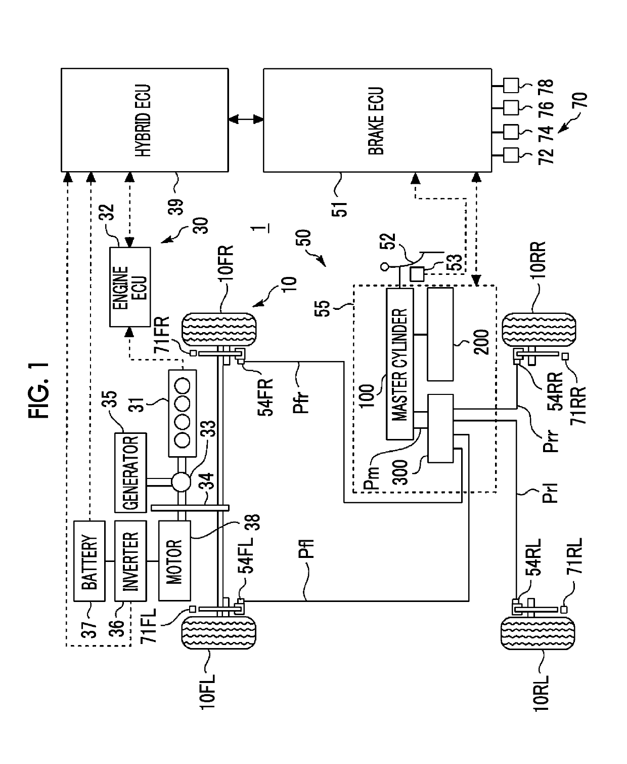
[0122]More specifically, based on the steering angle and a vehicle speed, the brake ECU 51 computes a target yaw rate by a known method. The steering angle is detected by the steering angle sensor 72. The vehicle speed is detected by the vehicle speed sensor 74. Alternatively, the vehicle speed may be computed from the rotational speeds of the front left wheel 10FL, the front right wheel 10FR, the rear left wheel 10RL, and the rear right wheel 10RR, which are respectively detected by the wheel speed sensors 71FL, 71FR, 71RL, 71RR. Furthermore, the brake ECU 51 computes a yaw rate deviation by subtracting the target yaw rate from the actual yaw rate. The actual yaw rate is detected by the yaw rate sensor 78. Then, the brake ECU 51 compares the yaw rate deviation...

second example

5-2. Second Example

[0124]In the above first example, when each of the rear wheels is locked and a slip amount of the rear wheel is increased, an oversteering tendency is promoted. In order to cancel a locked state of the rear wheel, the brake pressure of the locked rear wheel has to be reduced.

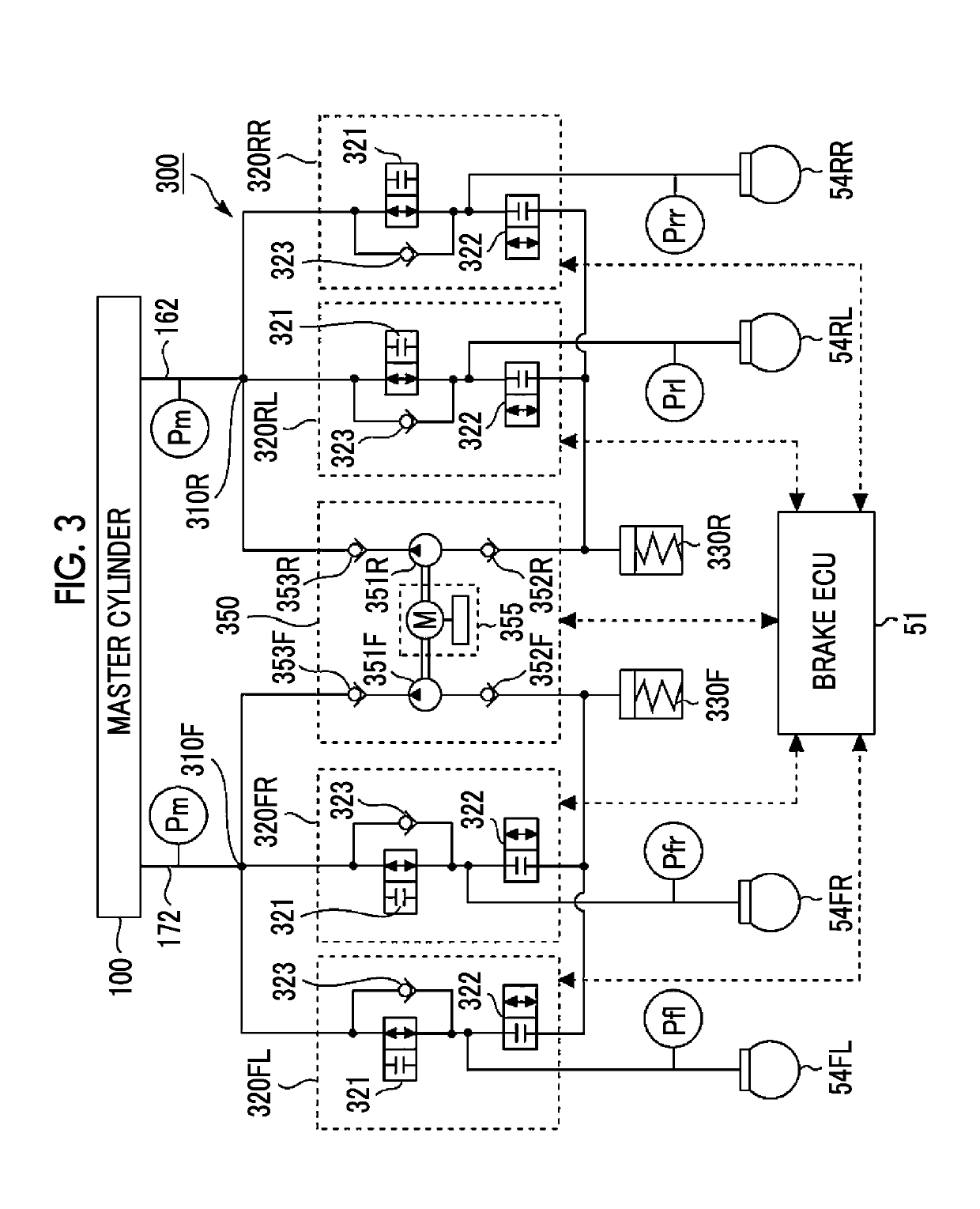
[0125]Here, it should be noted that the master pressure Pm has to be reduced in order to reduce the brake pressure in the pseudo mode. In a case of the pseudo mode, the brake pressure is not reduced using the reduction valve 322. This is because, as described above, the pumps 351F, 351R cannot be used and the reservoirs 330F, 330R are possibly full. However, when the master pressure Pm is reduced in order to cancel the locked states of the rear wheels, the brake pressure Pt of the target wheel 10T is also simultaneously reduced. As a result, the essential vehicle stability control is not executed as planned.

[0126]Accordingly, in the second example, locking of the rear wheels is prevented in ad...

third example

5-3. Third Example

[0127]A third example also has a purpose of preventing locking of the rear wheels in advance due to the same reason as the second example. However, in the third example, the outer rear wheel is also set as the target wheel 10T. That is, the target wheels 10T include both of the outer front wheel and the outer rear wheel. Furthermore, a boosted amount of the brake pressure of the outer rear wheel is set to be smaller than a boosted amount of the brake pressure of the outer front wheel.

[0128]A description will be made on one example of a method for changing the boosted amounts of the brake pressure between the outer front wheel and the outer rear wheel with reference to FIG. 8. In FIG. 8, a horizontal axis represents time, and a vertical axis represents pressure. Pof is the brake pressure of the outer front wheel, and Por is the brake pressure of the outer rear wheel. In the period from the time ts to the time te, the brake ECU 51 opens the booster valve 321 for the ...


PUM


Abstract

A brake control apparatus includes: a master cylinder that outputs a brake fluid at a master pressure; a master pressure changing device that is configured to change the master pressure irrespective of an operation of a brake pedal; a brake actuator; and a control unit that executes vehicle stability control by changing a brake pressure of a target wheel. Modes of the vehicle stability control include a normal mode and a pseudo mode. In the pseudo mode, the control unit operates the master pressure changing device such that the master pressure obtains a target value of the brake pressure of the target wheel, and changes the brake pressure of the target wheel in an interlocking manner with the master pressure. When the normal mode is unavailable, the control unit executes the vehicle stability control in the pseudo mode.

Description

INCORPORATION BY REFERENCE[0001]The disclosure of Japanese Patent Application No. 2016-156578 filed on Aug. 9, 2016 including the specification, drawings and abstract is incorporated herein by reference in its entirety.BACKGROUND1. Technical Field[0002]The present disclosure relates to a brake control apparatus for a vehicle. In particular, the present disclosure relates to a brake control apparatus that executes vehicle stability control.2. Description of Related Art[0003]A braking device for a vehicle is disclosed in Japanese Patent Application Publication No. 2015-136993 (JP 2015-136993 A). The braking device for the vehicle includes a master cylinder, a servo pressure generator, and a brake actuator. The servo pressure generator generates a servo pressure irrespective of an operation of a brake pedal by a driver. The master cylinder is operated on the basis of the servo pressure and outputs a brake fluid at master pressure that corresponds to the servo pressure to the brake actu...

Claims


Application Information

Patent Timeline
Patent Type & Authority Patents(United States)
IPC IPC(8): B60T8/1755B60T8/1761B60T8/26B60T8/44B60T7/12B60T13/14
CPCB60T8/17552B60T8/1761B60T8/26B60T8/44B60T2230/02B60T2270/30B60T7/12B60T13/146B60T8/1755B60T13/161B60T13/686B60T1/10B60T7/042B60T8/4077B60T13/662F16D61/00B60T2270/60
Inventor TANIMOTO, MITSUTAKA
Owner TOYOTA JIDOSHA KK
Why Eureka
Try Eureka