
Management of gear lash closure rate in a powertrain system

a technology of powertrain system and gear lash closure rate, which is applied in the direction of gearing details, mechanical equipment, transportation and packaging, etc., can solve the problems of reducing the accuracy of speed sensors in closed positions, difficult for controllers to accurately determine the status of lash state transition, and poor low-speed resolution of rotary speed sensors

Active Publication Date: 2019-11-26
GM GLOBAL TECH OPERATIONS LLC
View PDF5 Cites 0 Cited by
  • Summary
  • Abstract
  • Description
  • Claims
  • Application Information

AI Technical Summary

Benefits of technology

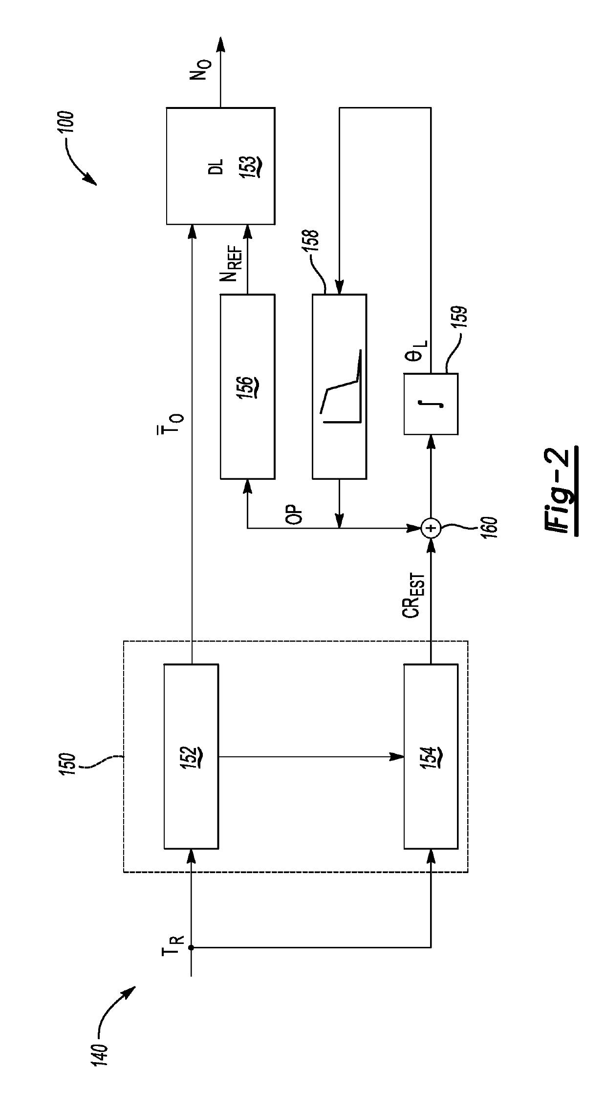
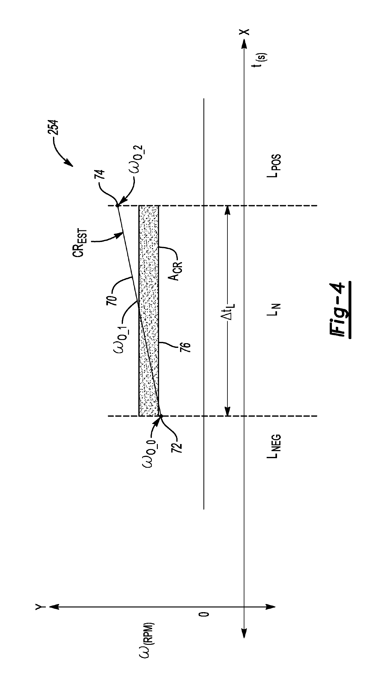
[0008]Execution of the instructions by a processor of the controller causes the processor to determine a requested output torque, and then process the requested output torque using an open-loop lash state model populated with a capped output torque request table and a lash closure rate estimate table. The tables respectively provide, in response to the requested output torque, a capped torque value and an estimated lash closure rate. The controller is also caused to calculate the output speed using a driveline plant model as a function of the capped torque value and the estimated lash closure rate, and thereafter to control a dynamic operating state of the powertrain during the lash state transition using the output speed to thereby manage the lash state transition.
[0017]Additionally, the controller is caused to apply a calibrated lash offset profile using the lash angle, with the lash offset profile having a magnitude that is higher at earlier stages of the lash state transition relative to later stages of the lash state transition. Thereafter, the controller calculates a reference speed of the electric traction motor using the lash offset profile, and uses the driveline plant model to calculate the output speed as a function of the capped torque value and the reference speed. A dynamic operating state of the powertrain is then controlled via speed or torque control of the electric traction motor during the lash state transition, using the output speed, to thereby manage the lash state transition.

Problems solved by technology

However, rotary speed sensors tend to exhibit relatively poor low-speed resolution.
As a result, it may be difficult for a controller to accurately determine the status of a lash state transition at all speeds when using sensor-based lash management strategies.
However, the reduced accuracy of speed sensors in closed-loop, sensor-based lash management approaches, when used with such low-inertia motors, may inhibit robust lash transition management.

Method used


Image

  • Management of gear lash closure rate in a powertrain system
  • Management of gear lash closure rate in a powertrain system
  • Management of gear lash closure rate in a powertrain system

Examples


Embodiment Construction

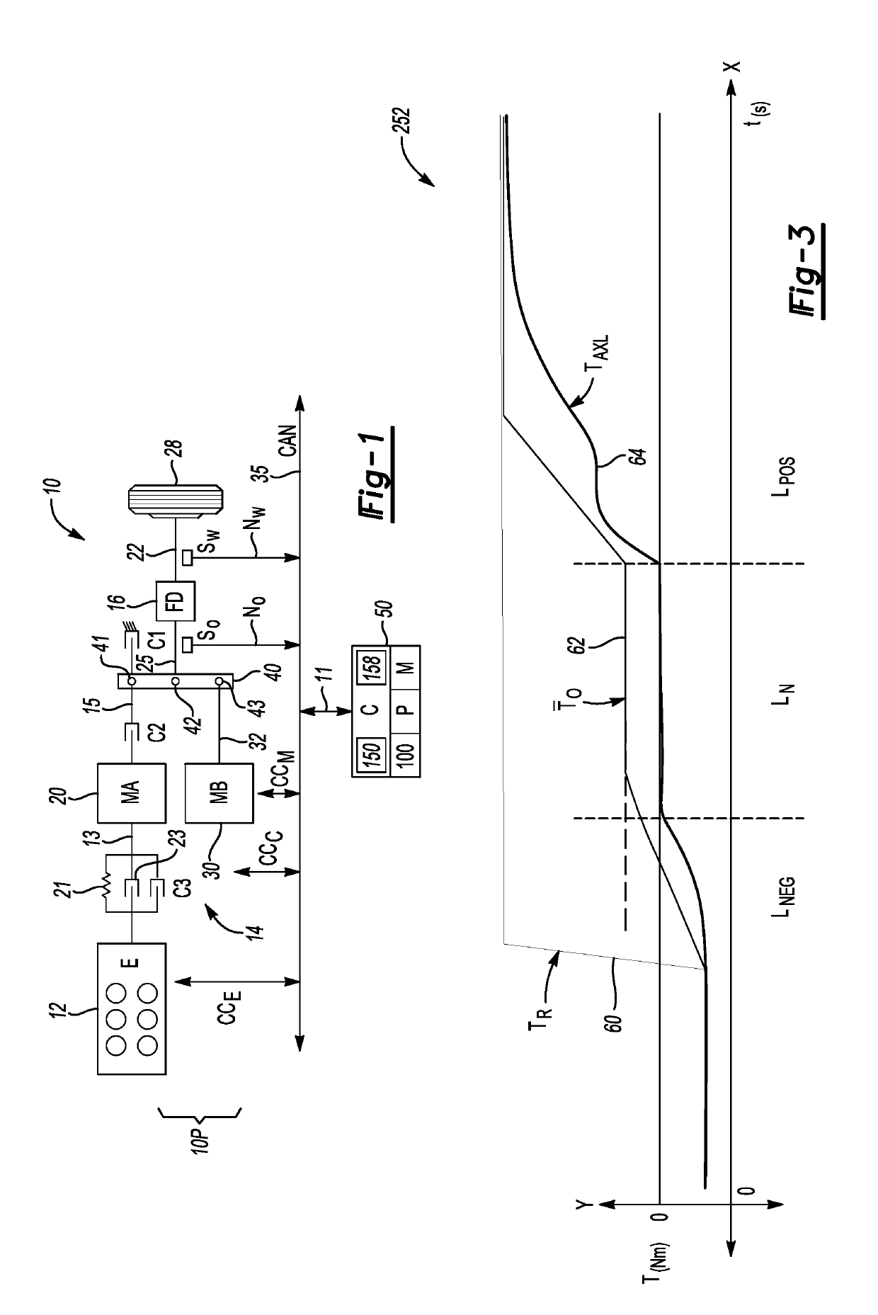
[0024]A vehicle 10 is shown schematically in FIG. 1. The vehicle 10 has a powertrain system 10P. The powertrain system 10P includes a controller (C) 50 and one or more driveline torque generating devices, shown as a representative internal combustion engine (E) 12 and first and second electric traction motors 20 and 30 (MA and MB, respectively). The powertrain system 10P also includes a transmission 14 and a final drive unit (FD) 16. The vehicle 10 of FIG. 1 is shown as an example hybrid electric vehicle which, in a non-limiting illustrative embodiment, uses the engine 12 in combination with the first and second electric traction motors 20 and 30. Fewer or additional electric motors may be used as part of the powertrain system 10P, either alone or in conjunction with the engine 12. Likewise, the engine 12 may be used as the sole source of driveline propulsion torque. For illustrative simplicity, the hybrid configuration of FIG. 1 will be described hereinafter without limiting the di...


PUM


Abstract

A powertrain system includes a transmission, torque generating device, load coupled to a drive axle, a final drive unit in meshed gear engagement with the output shaft and the drive axle, and a controller. A requested output torque is processed using an open-loop lash state model populated with a capped output torque request table and a lash closure rate estimate table respectively providing a capped torque value and an estimated lash closure rate. Output speed is determined using a plant model, the capped torque value, and the estimated lash closure rate. The powertrain is controlled during the transition using the output speed. A lash angle may be calculated from the closure rate using an integrator logic block. A calibrated lash offset profile may be determined using the lash angle, and a reference speed may be generated using the lash offset profile.

Description

INTRODUCTION[0001]Powertrain systems include one or more driveline torque generators, such as an internal combustion engine and / or one or more electric traction motors. Various powertrain components are placed in a meshed gear engagement with one another using splines or gear teeth. Driveline torque is transferred from the torque generator(s), through the meshed driveline components, and ultimately to a driven load. For instance, in a motor vehicle a set of drive wheels is disposed on one or more drive axles in meshed engagement with a differential gear set or final drive unit. An output shaft of a transmission ultimately powers the drive wheels through the intermeshed gears of the final drive unit and drive axle.[0002]The term “driveline lash” describes a condition that results from the play or slack in the above-noted meshed gear components. Slack may be present along the driveline due to manufacturing tolerances, which in turn facilitate component assembly, lubrication, thermal e...

Claims


Application Information

Patent Timeline
Patent Type & Authority Patents(United States)
IPC IPC(8): B60W30/20B60W10/08F16H63/50F16H57/00B60W10/06F16H59/14
CPCB60W30/20F16H63/50B60W10/08B60W10/06B60W2710/1094F16H2063/508B60Y2300/77B60Y2200/92F16H2059/144B60Y2300/72B60W20/10B60W50/00B60W2710/0666B60W2710/083B60W30/188B60W2710/0644B60W2050/0041B60W2710/081
Inventor LIU, CHIA-SHANGMORRIS, ROBERT L.
Owner GM GLOBAL TECH OPERATIONS LLC
Learn More