Seal structure of optical fiber drawing furnace, and method for drawing optical fiber

a technology of sealing structure and drawing furnace, which is applied in the direction of optical elements, manufacturing tools, instruments, etc., can solve the problems of increasing the use of inert gas etc., and the manufacturing cost of optical fiber cannot be decreased, so as to reduce the diameter of drawn optical fiber, reduce the load on the blade member, and prolong the life of the seal structure

Active Publication Date: 2019-11-26
SUMITOMO ELECTRIC IND LTD
View PDF11 Cites 1 Cited by
  • Summary
  • Abstract
  • Description
  • Claims
  • Application Information

AI Technical Summary

Benefits of technology

[0020]According to the seal structure of the optical fiber drawing furnace and the method for drawing the optical fiber of the invention, suction of the outside air inside the drawing furnace can be avoided and also, the amount of use of inert gas etc. can be decreased, and variations in diameter of the drawn optical fiber can be decreased. Also, a load on the blade member can be reduced, and the long-life seal structure can be provided.

Problems solved by technology

In this case, the outside air (oxygen) is prevented from entering the inside of the drawing furnace by setting the inside of the drawing furnace at positive pressure, but when airtightness is not obtained well in a gap between the glass preform and the upper end opening of the drawing furnace (the gap is not sealed), the outside air is sucked inside the drawing furnace to affect the life of the drawing furnace and also, the amount of use of the inert gas etc. is increased and a manufacturing cost of the optical fiber cannot be decreased.

Method used


Image

  • Seal structure of optical fiber drawing furnace, and method for drawing optical fiber
  • Seal structure of optical fiber drawing furnace, and method for drawing optical fiber
  • Seal structure of optical fiber drawing furnace, and method for drawing optical fiber

Examples


first embodiment

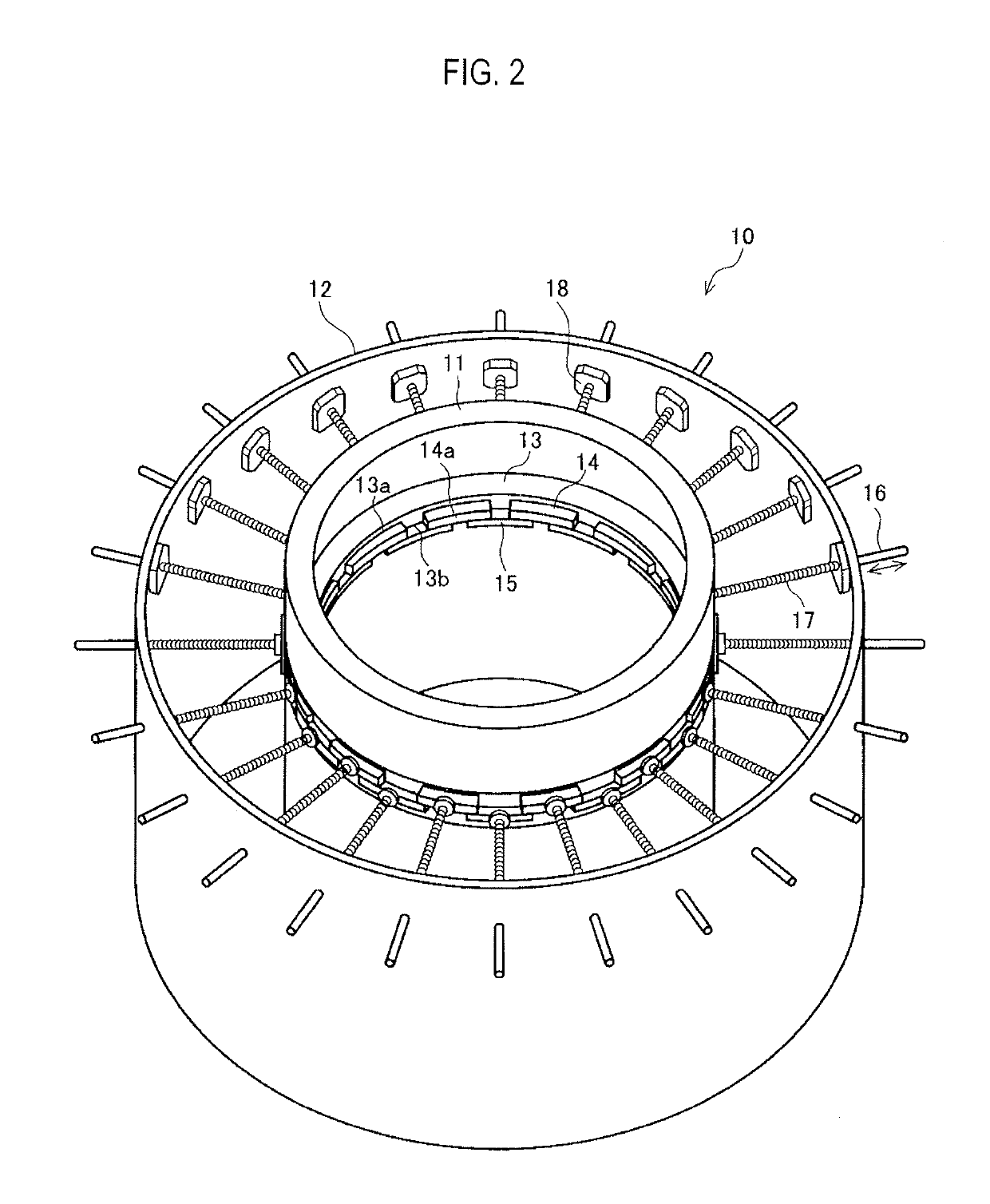
[0047]A seal structure according to a first embodiment of a seal mechanism will hereinafter be described with reference to FIG. 2. FIG. 2 is a perspective view showing an outline of a seal structure 10.

[0048]The seal structure 10 includes plural blade members 14, 15 with heat resistance, a cylinder 11 forming a part of a support mechanism for supporting the blade members 14, 15, and a mechanism (hereinafter called a pressing operation mechanism) having operation of inwardly pressing the blade members 14, 15. Hereinafter, the cylinder 11 is called an inside cylinder in order to distinguish the cylinder 11 from an outside cylinder 12 described below. In addition, the outside cylinder 12 forms a part of the support mechanism for supporting the blade members 14, 15.

[0049]The inside cylinder 11 includes plural guide holes 13a, 13b for sliding the plural blade members 14, 15 on the circumference of the inside cylinder 11, for example, in two steps alternately. The guide holes 13a, 13b are...

second embodiment

[0095]Next, a seal structure according to a second embodiment of a seal mechanism will be described with reference to FIGS. 7 to 10. FIG. 7 is a sectional view showing an outline of a seal structure 20, and FIG. 8 is a top view showing a main part of the seal structure of FIG. 7, and FIG. 9 is a diagram showing one example of a storage part of blade members in the seal structure 20, and FIG. 10 is a diagram showing one example of a cylindrical slit spring used in the seal structure 20.

[0096]The seal structure 20 of the second embodiment includes plural blade members 24, 25 with heat resistance, a storage part 23 forming a part of a support mechanism for supporting the blade members 24, 25, and a cylindrical slit spring 26.

[0097]As the blade members 24, 25, the same shape as that of the blade members 14, 15 described in the first embodiment etc. can be used, and each of the blade members 24, 25 has substantially a rectangular parallelepiped shape in which the cross-sectional shape in...

third embodiment

[0110]Next, a seal structure 30 according to a third embodiment of a seal mechanism will be described with reference to FIGS. 11, 12A and 12B. FIG. 11 is a sectional view showing an outline of the seal structure 30, and FIG. 12A and FIG. 12B shows a situation of the case where blade members in the seal structure of FIG. 11 are in opened and closed states, and FIG. 12A is a diagram showing a situation in which the blade members are in the opened state, and FIG. 12B is a diagram showing a situation in which the blade members are in the closed state (the most closed state).

[0111]The seal structure 30 includes plural blade members 34, 35 with heat resistance, an inclination table 31 for supporting the blade members 34, 35, and a support mechanism having a slide mechanism.

[0112]Also, the plural blade members 34, 35 and the support mechanism are placed and stored inside a housing 37 shown in FIG. 11. In addition, FIG. 11 illustrates a configuration in which upper and lower surfaces and a ...


PUM

PropertyMeasurementUnit
widthaaaaaaaaaa
widthaaaaaaaaaa
temperatureaaaaaaaaaa

Abstract

A seal structure of an optical fiber drawing furnace for sealing a gap between an upper end opening of the optical fiber drawing furnace and an optical fiber glass preform inserted from the upper end opening, includes a plurality of blade members, a support mechanism for supporting the plurality of blade members, and a pressing operation mechanism for individually pressing the plurality of blade members in a radial direction of the optical fiber glass preform so as to bring distal ends of the plurality of blade members into contact with a side surface of the optical fiber glass preform, wherein a pressing force at the time of bringing the plurality of blade members into contact with the optical fiber glass preform is set at 0.1 to 10 N per blade member.

Description

TECHNICAL FIELD[0001]The present invention relates to a seal structure of an optical fiber drawing furnace for closing a gap between an optical fiber glass preform and an upper end opening of the optical fiber drawing furnace, and a method for drawing an optical fiber.BACKGROUND ART[0002]An optical fiber is manufactured by downwardly moving a quartz-based optical fiber glass preform (hereinafter called a glass preform) from an upper end opening of an optical fiber drawing furnace (hereinafter called a drawing furnace) to the inside of a furnace core tube and also heating and melting the distal end of the glass preform and decreasing the diameter of the distal end of this glass preform and being drawn from a lower end opening. Since the temperature of the inside of the drawing furnace at this time becomes very high (about 2000° C.), carbon with good heat resistance is used in a component of the inside of the drawing furnace.[0003]This carbon has properties oxidized and consumed in a ...

Claims


Application Information

Patent Timeline
Patent Type & Authority Patents(United States)
IPC IPC(8): C03B37/029G02B6/00C03B37/027
CPCG02B6/00C03B37/029C03B37/027C03B2205/80
Inventor YAMAZAKI, TAKASHIOKAZAKI, IWAOKONISHI, TATSUYA
Owner SUMITOMO ELECTRIC IND LTD
Why Eureka
Try Eureka