
Highly efficient wood stove/heater

a wood stove and high-efficiency technology, applied in the field of high-efficiency rocket heaters, can solve the problems of high operating costs of electric heaters, and inefficient heating of structures and occupants, and achieve the effects of high efficiency, clean burning, and present invention

Active Publication Date: 2019-12-03
LIBERATOR LLC
View PDF4 Cites 0 Cited by
  • Summary
  • Abstract
  • Description
  • Claims
  • Application Information

AI Technical Summary

Benefits of technology

The present invention is a heater that is ideal for individuals and families who adhere to self-sufficient living, homesteading, and off-grid living forums. It is designed to use ¼ of the wood typically used in traditional wood stoves and is one of the cleanest burning wood stoves available. The high efficiency of the invention is achieved through a maximization of draft and thermodynamic heat transfer, which includes convection, conduction, and radiation. The design is also critical to maximize the draft, which allows the stove to create a ‘forge’ effect. The geometrical concept of the invention is important in facilitating a strong draft towards the flame. The heater is equipped with an internal chimney, which only permits cooler gases to vent to the bottom of the stove through the chimney. This design also allows for a longer burn time for the wood, improving its efficiency.

Problems solved by technology

While both methods provide heat to the structure and its occupants, neither are very efficient.
Electric heaters, especially those powered via an HVAC unit can be expensive to operate, and much of the heat is lost through ducting and poor insulation.
Conventional systems such as these are often difficult to maintain, are overly complex, and are very expensive.
Additionally, many do not employ a down-draft burn principle.
While masonry heaters are efficient, they are not practical for use in conventional homes and business.
Most building codes do not allow this, and it is often difficult to insure.
As such, these masonry heaters are not viable options for most customers.
Heaters that employ principles similar to that of masonry heaters are known to be expensive, and are often unsafe for use in conventional structures.
Due to this expense, it is presently uncommon for similar heaters to be installed in conventional structures such as residences.
Chainsaws, which are conventionally gasoline powered, which partially defeats some of the benefits of heating with wood), are the number one tool involved in on-the-job accidents in North America.
Conventional axes are not much safer than chainsaws.

Method used


Image

  • Highly efficient wood stove/heater
  • Highly efficient wood stove/heater
  • Highly efficient wood stove/heater

Examples


Embodiment Construction

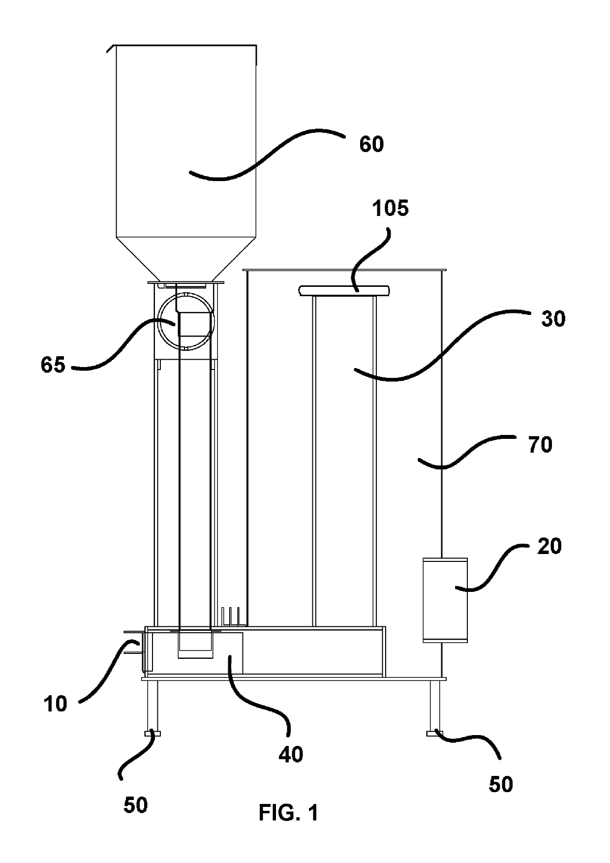
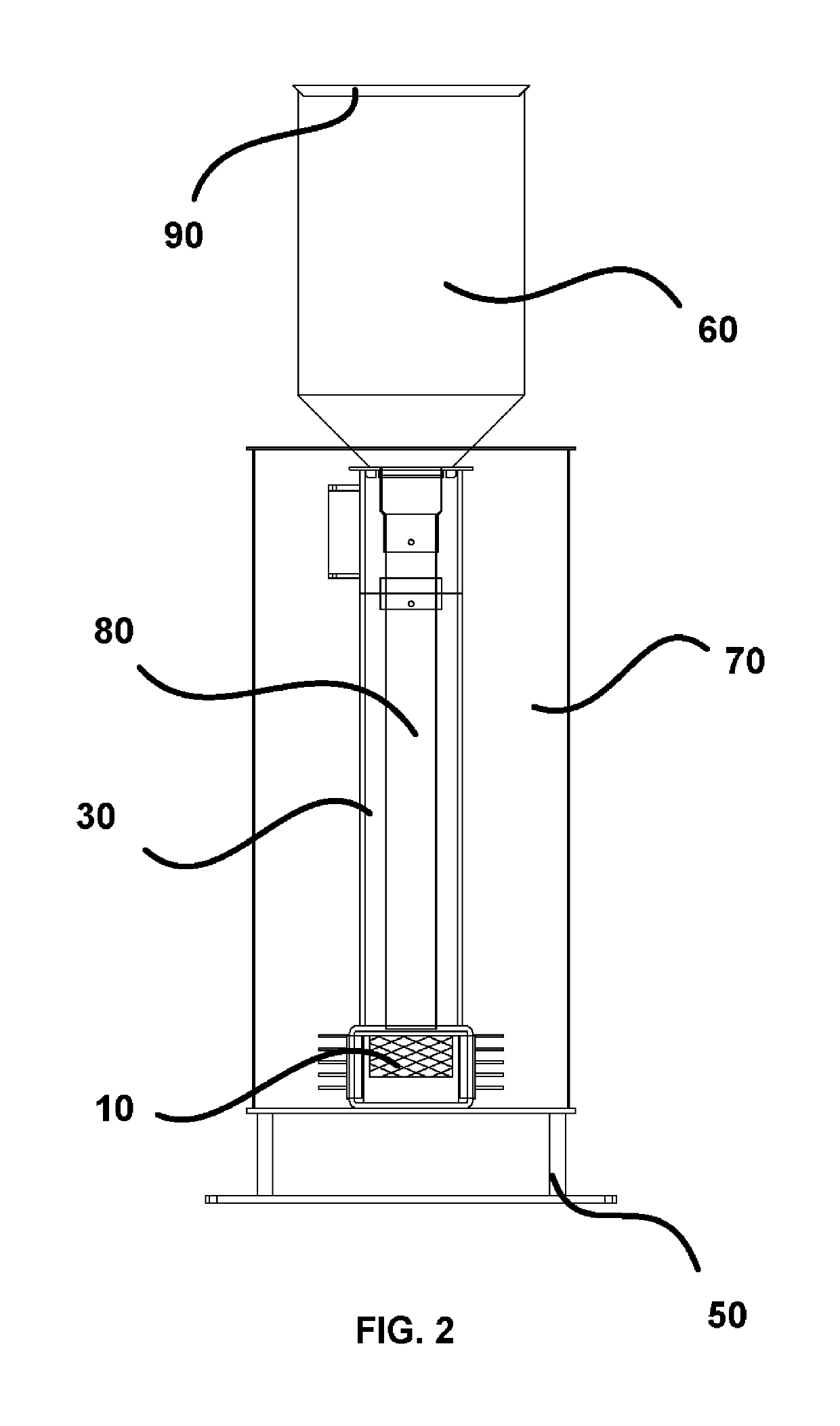
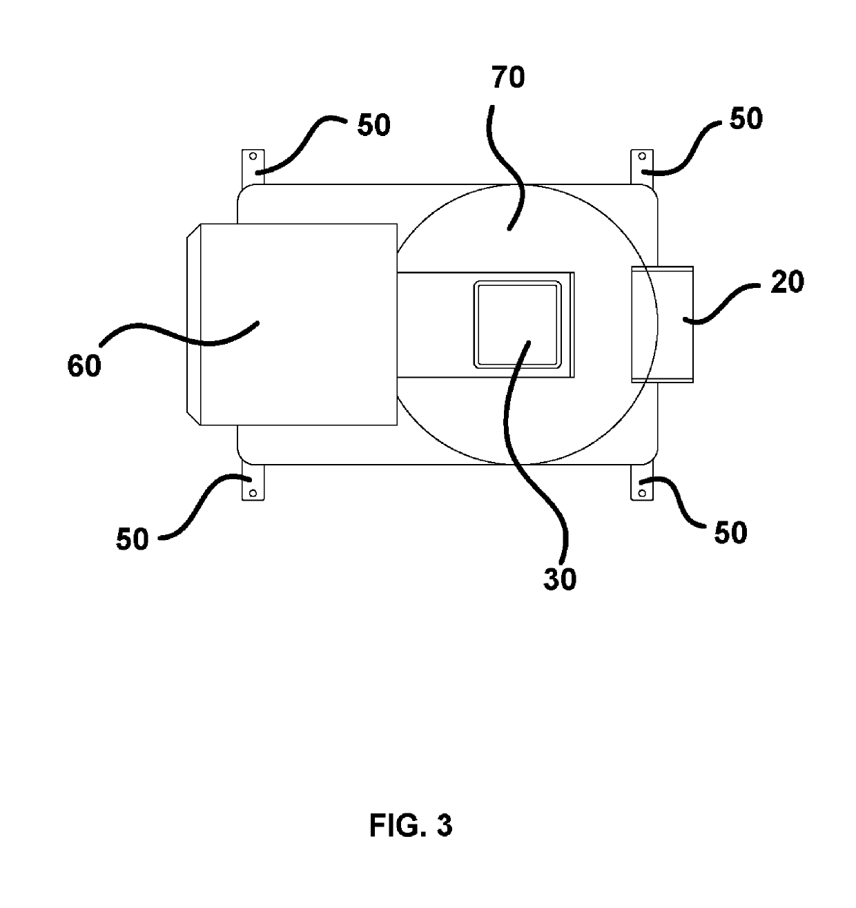
[0026]The present invention is a highly efficient indoor heater system configured for safe use within a home, business, or other structure equipped with a chimney. The present invention is equipped with a front access door (10), at least one exhaust (20), and internal chimney (30), a stove combustion area (40) (known to be a combustion chamber), a convection chamber (70), a gravity-fed fuel chute (80), and support struts (50). Most of the construction of the present invention is fashioned of metallic alloys capable of withstanding heat of over 1000 degrees Fahrenheit. Some embodiments of the present invention are preferably equipped with a pellet hopper (60), which is configured to feed fuel pellets into the gravity-fed fuel chute (80) to supply fuel to the fire. The pellet hopper (60) is preferably equipped with a pellet hopper lid (90), which ensures that the system remains closed, and that cool outside air does not enter the structure. When the pellet hopper (60) is not used, a c...


PUM


Abstract

A highly efficient indoor heating system and device is described. The device is equipped with an internal chimney, as well as vents that are configured to maximize the draft applied to the flame housed within a stove combustion area. The heater is configured to reach temperatures exceeding 300 degrees Fahrenheit in approximately ten minutes. A gravity fed fuel tube, potentially in communication with a wood pellet hopper, is configured to deliver fuel to the stove of the heater. Heat is distributed throughout the structure of the device, and a convection chamber within the device ensures that heat generated is not quickly lost via exhaust.

Description

[0001]This application is a non-provisional application of provisional patent application No. 62 / 426,093, filed on Nov. 23, 2016, and priority is claimed thereto.FIELD OF THE PRESENT INVENTION[0002]The present invention is related to non-electric heating devices, and more specifically relates to a highly efficient “rocket heater” configured to employ a gravity-fed fuel system equipped with an internal chimney, durable proprietary components including a downdraft burn grate employing a down-draft combustion principle, and an off-set heat riser for optimal thermal conduction of heat into the structure.BACKGROUND OF THE PRESENT INVENTION[0003]Conventionally, homes, businesses, and other structures that exist outside of the tropics are equipped with at least one heater. Often, the heater is electric, and may be built into the HVAC system of the structure. Other structures employ a fireplace, which requires someone to tend to a fire consistently in order to ensure constant and consistent...

Claims


Application Information

Patent Timeline
Patent Type & Authority Patents(United States)
IPC IPC(8): F23B30/00F23L15/04F23B80/00F23B50/12F23G7/10F23C1/04F23C1/02F23B50/06F24B5/04
CPCF23C1/02F23B50/06F23G7/105F23C1/04F23B1/26F24B5/04F23B7/005F23B50/12F23B80/00F23L15/04F23J2219/10F23G2900/50002F23B2900/00001F23G2206/00Y02E20/34
Inventor HUDDLESTON, SKYHUDDLESTON, PHILLIP M.
Owner LIBERATOR LLC
Learn More