Displacement estimation method and thermal displacement correction method for machine tool

a technology of displacement estimation and machine tool, which is applied in the direction of electric programme control, program control, instruments, etc., can solve the problems of large displacement, deformation of the machining accuracy of the workpiece, and deformation of the relative position between the tool and the workpiece, so as to achieve accurate estimation of the influence of the heat of vaporization and the temperature change due to heat of vaporization , the effect of reducing the temperatur

Active Publication Date: 2019-12-03
OKUMA CORP
View PDF16 Cites 2 Cited by
  • Summary
  • Abstract
  • Description
  • Claims
  • Application Information

AI Technical Summary

Benefits of technology

[0031]According to the present invention, a temperature of a portion of which the temperature is difficult to directly measure and to which the temperature sensor is not attached can be accurately estimated in a simple method, on the basis of a result of temperature measurement at a portion to which the temperature sensor is attached.
[0041]According to the eighth aspect of the present invention, by setting the time constant according to a kind of a workpiece, a tool, or the like, the temperature change thereof can be estimated. Even when the workpiece, the tool, or the like is changed, the temperature change can be accurately estimated.

Problems solved by technology

Such thermal displacement may cause a relative position between a tool and a workpiece to be changed.
Therefore, if thermal displacement occurs in the machine tool during machining, machining accuracy for the workpiece may be degraded.
In a case where a coolant is used, large displacement occurs, in some cases, due to rapid temperature change caused by difference in temperature between the coolant and the workpiece or a structure when discharging is started.
Due to these influences, large displacement may occur when the machining is restarted.
However, a machine tool has many rotary portions and movable portions, and measurement of temperatures is difficult in many portions due to restriction by wiring and the like.
Further, it is difficult to directly measure temperatures of a workpiece and a tool that are attached to or detached from the machine tool.
Therefore, accuracy for estimating thermal displacement is reduced, and a correction error may be increased.
Further, the portion of which the temperature is difficult to measure, is a portion which is likely to be influenced by a coolant in many cases, whereby the correction error tends to be further increased.
In a case where machining is performed without using a coolant, difference in temperature between the turret head and the temperature simulation block is increased due to difference in ambient environment, and a correction error may be increased.
Further, when machines are changed and the size of the turret head is changed, the temperature simulation block needs to be also changed according to the size of the turret head, and labor and time may be increased in designing and manufacturing of the machine tool.
However, it is difficult to use this method in practice in some points.
However, it may be difficult to simply adjust a coefficient based on the difference in temperature between the spindle and the coolant in practice.
Further, Patent Literature 2 discloses a method for improving, in a transient state, change after use of a coolant is ended, but does not provide description about change after start of discharging.
In the method disclosed in Patent Literature 3, difference between a case where a coolant is used and a case where no coolant is used, is not considered, and a correction error may be increased in a case where no coolant is used.

Method used


Image

  • Displacement estimation method and thermal displacement correction method for machine tool
  • Displacement estimation method and thermal displacement correction method for machine tool
  • Displacement estimation method and thermal displacement correction method for machine tool

Examples


Embodiment Construction

[0047]Hereinafter, an embodiment of the present invention will be described with reference to the drawings.

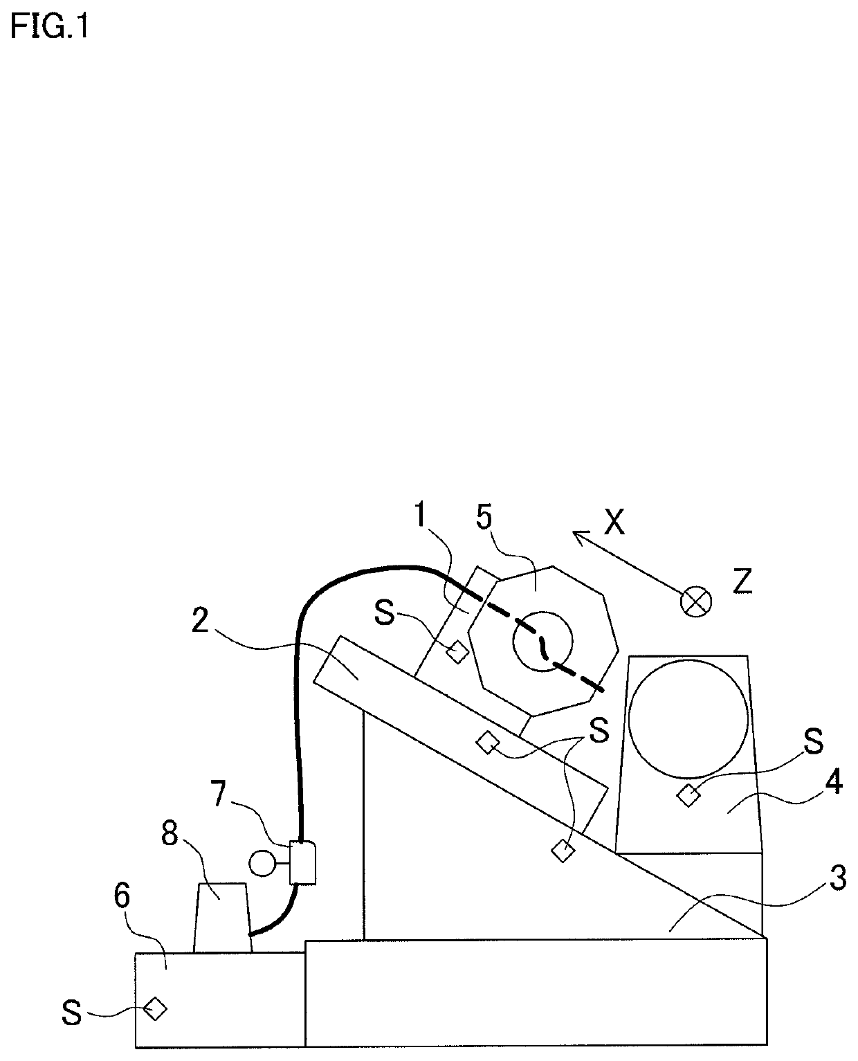
[0048]FIG. 1 illustrates an NC lathe that is an example of a machine tool. Needless to say, the present invention is also applicable to other types of machine tools such as a machining center and a combined machining tool.

[0049]The NC lathe shown in FIG. 1 includes a cutting tool holder 1, a saddle 2, a bed 3 that is a base, and a headstock 4. Temperature sensors S, S, . . . are attached to each of the cutting tool holder 1, the saddle 2, the bed 3, and the headstock 4 (portions to which the temperature sensors are attached). Further, the cutting tool holder 1 has a turret 5 mounted thereto, and the turret 5 has a plurality of tools previously mounted thereto, and can rotate to change a tool to be used. The temperature sensor is not attached to the turret 5 (portion to which the temperature sensor is not attached). This is because the turret 5 is a rotary portion and wiring is ...


PUM


Abstract

A temperature of a portion of which the temperature is difficult to directly measure is accurately estimated in a simple method.In S1, information about a coolant discharging / stopping state is obtained. As the information about the coolant discharging / stopping state, a flag is used such that the flag represents 1 for the discharging state and the flag represents 0 for the stopping state. Next, in S2, temperature data is obtained from temperature sensors provided in components of a machine tool, a machining space, and a coolant tank. Next, in S3, lag process is performed for the coolant discharging / stopping state flag, and coefficients for measured temperatures of the coolant and the structure are calculated. Next, in S4, the measured temperatures are multiplied by the coefficients, and an estimated temperature of a portion to which the temperature sensor is not attached is calculated.

Description

[0001]This application claims the benefit of Japanese Patent Application Number 2016-249626 filed on Dec. 22, 2016, the entirety of which is incorporated by reference.BACKGROUND OF THE INVENTION[0002]Field of the Invention[0003]The present invention relates to a method for estimating, in a machine tool, a temperature of a portion of which the temperature cannot be directly detected by temperature detection means such as a temperature sensor, and a method for correcting thermal displacement according to the estimated temperature.[0004]Description of the Background Art[0005]In a case where machining is performed by using a machine tool, thermal deformation may be caused in components of the machine tool due to, for example, mechanical heat generation by, for example, spindle and feed shaft operations, and due to temperature change of an environment in which the machine tool is installed, or temperature change of a coolant. Such thermal displacement may cause a relative position betwee...

Claims


Application Information

Patent Timeline
Patent Type & Authority Patents(United States)
IPC IPC(8): G05B19/404B23Q11/00B23Q15/18
CPCG05B19/404B23Q11/0007B23Q15/18B23Q2220/006G05B2219/49206B23Q11/10B23Q17/0985G05B19/4103
Inventor MIZOGUCHI, YUJI
Owner OKUMA CORP
Why Eureka
Try Eureka