Eureka AIR delivers breakthrough ideas for toughest innovation challenges, trusted by R&D personnel around the world.

Transmission shaft and peripheral structure

a technology of transmission shaft and peripheral structure, which is applied in the direction of shaft and bearings, rotary combination bearings, rotary bearings, etc., can solve the problems of reducing waterproof effect, affecting the rotation of transmission shaft, and affecting the operation of transmission shaft, so as to reduce friction between transmission shaft and other components, improve waterproof effect, and not reduce waterproof function

Active Publication Date: 2019-12-10
FAIRWAY ELECTRONICS
View PDF4 Cites 0 Cited by
  • Summary
  • Abstract
  • Description
  • Claims
  • Application Information

AI Technical Summary

Benefits of technology

The present invention provides a transmission shaft and peripheral structure that can prevent water from entering while still allowing the shaft to rotate freely. This is achieved by using two gaskets, one to cover the gap below the bearing and one to cover the gap above the bearing, with silicone oil filled between them. The silicone oil bonds the gaskets and fills the gaps, preventing liquid from entering. This design eliminates the need for tight fitting of the gaskets with the shaft, reducing wear and tear that can occur with tight fitting. The transmission shaft and peripheral structure can also include additional washers to further improve waterproof effect.

Problems solved by technology

However, it will hinder the rotation of the transmission shaft.
Moreover, the washer or gasket will be worn and the waterproof effect will be reduced after a period of time.
Therefore, how to provide a transmission shaft and peripheral structure that can avoid hindering the rotation of the transmission shaft and achieve waterproof effect has become an urgent problem to be solved by the industry.

Method used


Image

  • Transmission shaft and peripheral structure
  • Transmission shaft and peripheral structure
  • Transmission shaft and peripheral structure

Examples


first embodiment

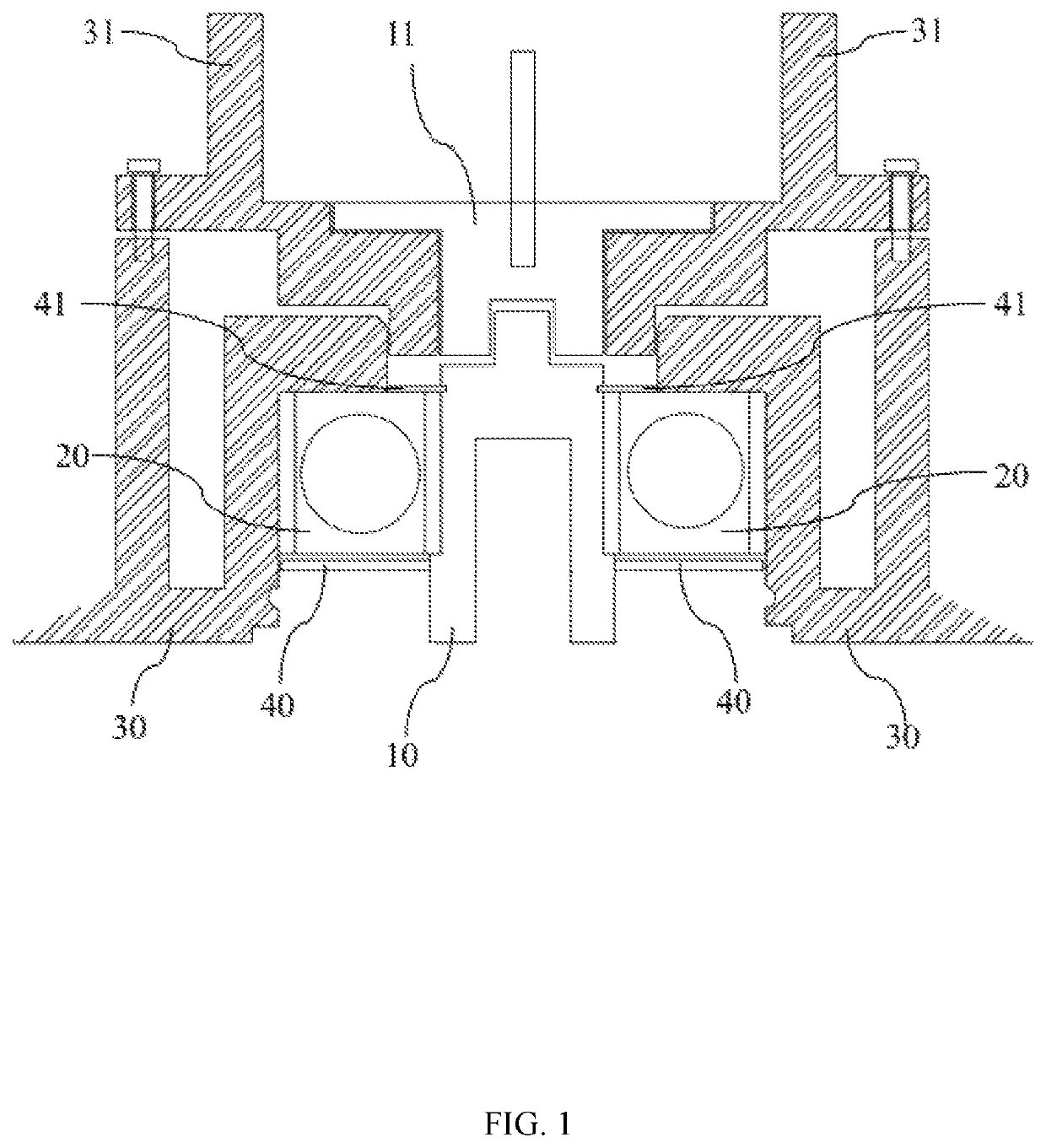
[0023]Please refer to FIG. 1. FIG. 1 illustrates a schematic diagram of a structure of a transmission shaft and peripheral structure according to the present invention. As shown, the transmission shaft and peripheral structure according to the present invention comprises a first rotating shaft 10, a bearing 20, a first frame 30, a second rotating shaft 11, a second frame 31, a first gasket 40 and a second gasket 41. The transmission shaft and peripheral structure according to the present invention mainly applied to the field of handheld tools.

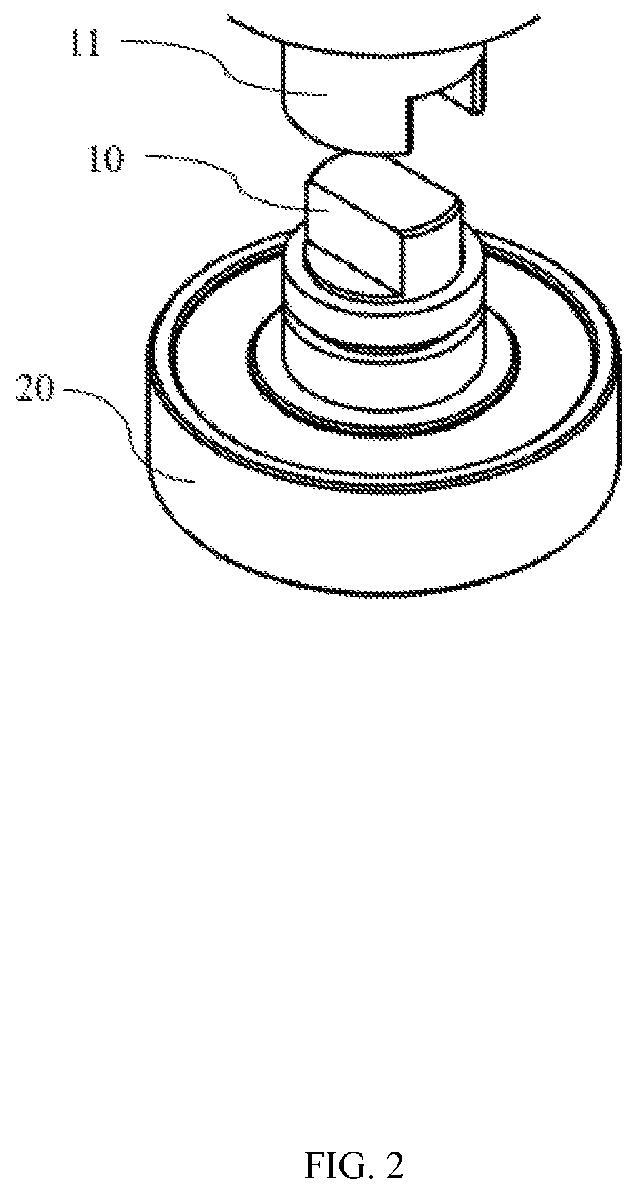
[0024]The bearing 20 is connected to the first rotating shaft 10. The bearing 20 is used for supporting the first rotating shaft 10 and maintaining the position when the first rotating shaft 10 rotates. In an embodiment, the inside of the bearing 20 is filled with silicone oil or lubricating oil. The first rotating shaft 10 can be directly or indirectly connected with a tool part (such as a grinding disc or a drill bit, etc.).

[0025]The second r...

second embodiment

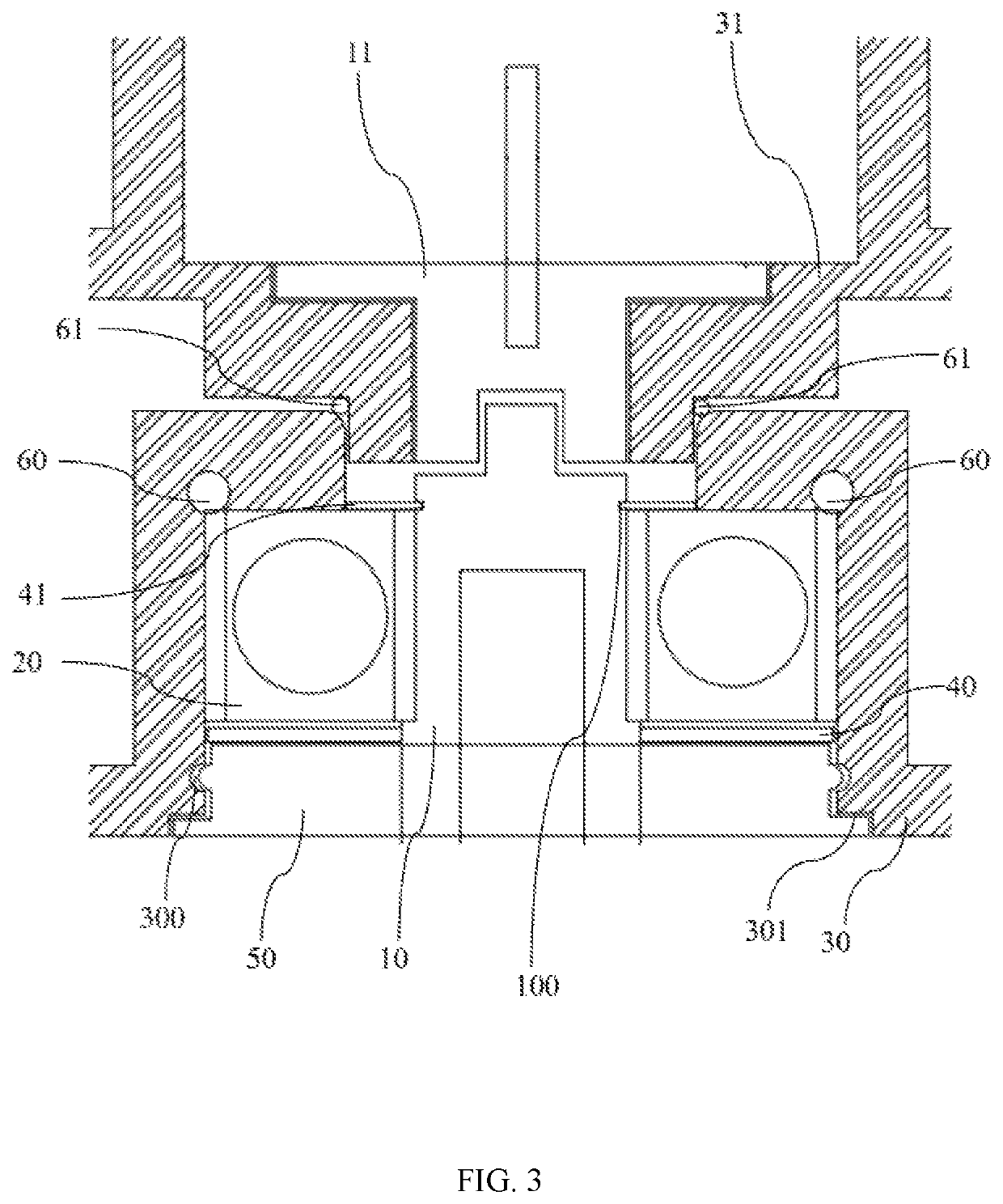
[0031]Please refer to FIG. 3. FIG. 3 illustrates a schematic diagram of a structure of a transmission shaft and peripheral structure according to the present invention. In an embodiment, the first rotating shaft 10 has a groove 100 corresponding to the second gasket 41. The groove 100 helps to further improve the waterproof function, and silicone oil can also be filled in the groove 100.

[0032]In an embodiment, the transmission shaft and peripheral structure according to the present invention further comprising a cover 50 connected to the first frame 30 and adjacent to the first gasket 40, and silicone oil being filled between the cover 50 and the first gasket 40. The cover 50 can further improve the waterproof function and protect the internal components. The cover 50 can also support and maintain the position of the bearing 20 and the first gasket 40.

[0033]In an embodiment, the first frame 30 has at least one groove 300, 301 corresponding to the cover 50. The grooves 300, 301 can i...


PUM


Abstract

A transmission shaft and peripheral structure comprises a first rotating shaft, a bearing, a first frame, a second rotating shaft, a second frame, a first gasket and a second gasket. The bearing is connected to the first rotating shaft. The first frame is connected to the bearing. The second rotating shaft is used for driving the first rotating shaft when the second rotating shaft rotates. The second frame is connected to the second rotating shaft. The first gasket is disposed under the bearing to cover the gap below the bearing. The second gasket is disposed above the bearing to cover the gap above the bearing. Silicone oil is filled between the first gasket and the bearing and between the second gasket and the bearing.

Description

RELATED APPLICATIONS[0001]The present application claims the priority of Taiwan Application No. 107127587, filed on Aug. 8, 2018, the disclosure of which is hereby incorporated by reference herein in its entirety.BACKGROUND OF THE INVENTION1. Field of the Invention[0002]The present disclosure generally relates to a transmission shaft and peripheral structure, and, more particularly, to a transmission shaft and peripheral structure applied to a handheld tool.2. Description of the Related Art[0003]In general, a handheld tool consist of a motor, a transmission, a tool part, and a housing. In the design of a transmission shaft and peripheral structure, the transmission shaft is generally connected to the inside of the bearing and the outside of the bearing is connected to the housing. Due to the gap of the connection portion between the housing and the upper and lower sides of the bearing, the peripheral structure of the transmission shaft and the transmission shaft will be the design f...

Claims


Application Information

Patent Timeline
IPC IPC(8): F16C33/66F16C33/78F16C19/16
CPCF16C19/16F16C33/782F16C33/664F16C21/00F16C33/6688F16C33/763F16C33/783F16C2322/50
Inventor YEN, LIN-HANHSIEH, CHIEN-HSIUNG
Owner FAIRWAY ELECTRONICS
Why Eureka
Eureka Blog
Learn More