Method for controlling an energy storage system

a technology of energy storage system and energy storage capacity, applied in the direction of battery/fuel cell control arrangement, indicating/monitoring circuit, transportation and packaging, etc., can solve the problem of reducing the charge capability and discharge capability of the oldest battery module, the risk of providing a charge current, and the temperature of the warmer battery module. achieve the lowest maximum power capability, reduce the risk of providing a charge current, and cost efficient

Active Publication Date: 2019-12-10
VOLVO TRUCK CORP
View PDF15 Cites 2 Cited by
  • Summary
  • Abstract
  • Description
  • Claims
  • Application Information

AI Technical Summary

Benefits of technology

[0012]An advantage of the present invention is that the applied charge current is directly dependent on, and proportional to, the maximum power capability of the battery module having the lowest power capability. Hereby, the battery module having the lowest power capability sets the limit for the charge current which reduces the risk of providing a charge current being damageable to the battery module. Also, by providing a charge current as described above, there is no need to individually controlling all of the at least two battery modules, i.e. it is only the battery module with the lowest power capability that is controlled while the remaining battery modules of the energy storage system receive their charge current dependent on the battery module having the lowest power capability. Hereby, a cost efficient method is provided in comparison to the above described prior art solution, since there is no need of controlling each of the battery modules.
[0013]According to an example embodiment, the method may be further followed by the steps of measuring a battery charge level of the battery module having lowest maximum power capability; and adjusting the charge current for reducing a difference between the battery charge level of the battery module having the lowest maximum power capability and the power threshold limit.
[0014]Hereby, the battery module having the lowest, power capability may be utilized to its optimum limit. As an example, if one of the battery modules in the energy storage system is exchanged with a new one, the power capability of the older battery may be smaller in comparison to the new battery module. Also, the resistance of the older battery module may, most likely, be larger than the new battery module. Hereby, when the charge current, which level is being proportional to the power capability of the older battery module, is provided to the parallel coupled battery modules, the older battery may not receive power up to its maximum power capability. In order to utilize the older battery module optimally, the charge current is adjusted, i.e. increased, such that the difference between charge current for the older battery module and the power threshold limit is reduced. Naturally, the remaining battery modules of the energy storage system, i.e. the battery modules having a larger maximum power capability than the older battery module, will also receive an increased charge current. Accordingly, the overall performance of the energy storage system will be increased.
[0015]According to another example, if one of the battery modules of the energy storage system has an increased temperature level in comparison to the remaining battery modules, i.e. it is warmer than the remaining battery modules; the resistance of the warmer battery module will most likely be lower in comparison to the remaining battery modules. When the charge current is applied there is hence a risk that the warmer battery module will receive a charge current which corresponds to a power level which is higher than its maximum power capability, i.e. the warmer battery module may receive more charge current than it can handle. This may, for example, result in the battery module being aged more rapidly. By adjusting the charge current, in this example to be lower than the originally provided charge current, will then provide for an increased operational lifetime of the warmer battery module, as well as to prevent that the temperature is increased even further. Also, the operational lifetime of the entire energy storage system may be increased.
[0016]According to an example embodiment, the step of adjusting the charge current may comprise the steps of iteratively receiving battery charge level information from the battery module having the lowest maximum power capability and adjusting the charge current until the difference between the battery charge level of the battery module having the lowest maximum power capability and the power threshold limit is within a predetermined limit value.
[0017]By iteratively receiving battery charge level of the battery module and adjusting the applied charge current based on the received battery charge level information enables the method to increase / decrease the charge current in small steps, i.e. “little by little”. Hereby, the difference between the battery charge level of the battery module having the lowest maximum power capability and the power threshold limit can be made with further accuracy.

Problems solved by technology

However, a problem with energy storage systems having parallel coupled battery modules is that the battery modules need to be in approximately the same physical state for optimal energy usage.
It is however a common scenario that the battery modules / battery packs are not in the same physical state and as an example, if the parallel coupled battery modules are differently aged, i.e. one of the battery modules has been recently exchanged with a new and unused battery module, there will most likely be a difference in power capability between the differently aged battery modules, which in turn will result in a reduced charge capability and discharge capability for the oldest battery module.
Hereby, there is a risk that the warmer battery module will receive a charge current which is higher than its capability.
Hereby, the battery module having the lowest power capability sets the limit for the charge current which reduces the risk of providing a charge current being damageable to the battery module.
Hereby, when the charge current, which level is being proportional to the power capability of the older battery module, is provided to the parallel coupled battery modules, the older battery may not receive power up to its maximum power capability.
When the charge current is applied there is hence a risk that the warmer battery module will receive a charge current which corresponds to a power level which is higher than its maximum power capability, i.e. the warmer battery module may receive more charge current than it can handle.
This may, for example, result in the battery module being aged more rapidly.

Method used


Image

  • Method for controlling an energy storage system
  • Method for controlling an energy storage system
  • Method for controlling an energy storage system

Examples


Embodiment Construction

[0034]The present invention will now be described more fully hereinafter with reference to the accompanying drawings, in which exemplary embodiments of the invention are shown. The invention may, however, be embodied in many different forms and should not be construed as limited to the embodiments set forth herein; rather, these embodiments are provided for thoroughness and completeness. Like reference characters refer to like elements throughout the description.

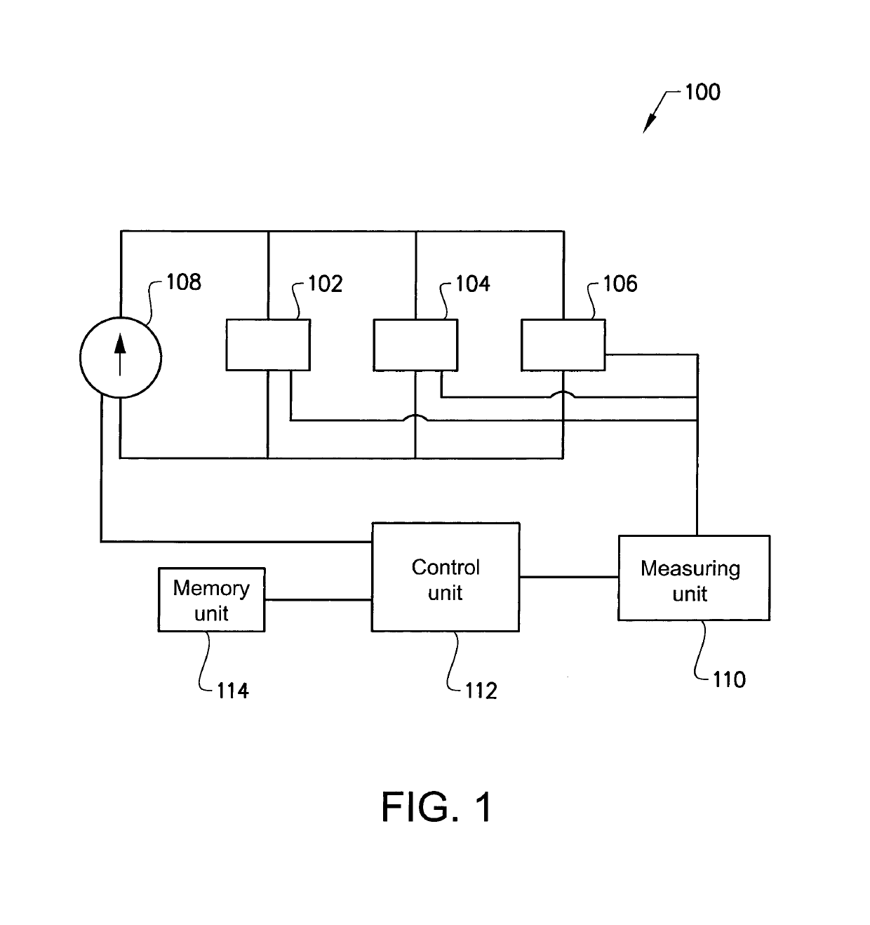
[0035]Turning to FIG. 1, which illustrates an example embodiment of an energy storage system 100 according to the present invention. The energy storage system 100 depicted in FIG. 1 comprises a first 102, a second 104, and a third 106 battery module. The battery modules 102, 104, 106 are coupled in parallel to each other and are further connected to a generator 108 configured to generate electric current for charging the parallel coupled battery modules 102, 104, 106. The wording “battery module” should in the following and ...


PUM


Abstract

A method is provided for controlling an energy storage system, the energy storage system including at least two battery modules electrically coupled in parallel to each other. The method includes receiving a signal indicative of a maximum power capability of each of the respective battery modules; assigning a power threshold limit for the at least two battery modules of the energy storage system corresponding to the lowest maximum power capability received from the battery modules; and providing a charge current to the at least two battery modules, the charge current having a current level being proportional to the power threshold limit.

Description

BACKGROUND AND SUMMARY[0001]The present invention relates to the field of energy storage systems, and in particular to a method for controlling an energy storage system having battery modules coupled in parallel, in order to optimize the power utilization of the battery modules. The invention also relates to a corresponding control unit adapted to control the energy storage system.[0002]Within the field of battery systems, energy storage systems are frequently used in a wide variety of applications and fields of technology. In, for example, the automotive industry, energy storage systems may be used for propulsion of a vehicle as well as to provide electrical energy to various systems of the vehicle.[0003]In order to increase the power capability of the energy storage system, a solution can be provided where two or more battery modules / battery packs of the energy storage systems are coupled in parallel to each other. Hereby, the individual battery modules can be easily connected to,...

Claims


Application Information

Patent Timeline
Patent Type & Authority Patents(United States)
IPC IPC(8): H02J7/00H02J7/04H02J7/14B60L58/13B60L58/15B60L58/22
CPCB60L58/13H02J7/0021B60L58/15H02J7/0018H02J7/0014B60L58/22H02J7/1423H02J7/0022H02J7/045H02J7/0077Y02T10/7044H02J2007/005B60L2240/545H02J2007/0096Y02T10/7005Y02T10/7061B60L2240/549B60L2240/547H02J7/0048H02J7/00712Y02T10/70H02J7/04H02J7/005H02J7/00034
Inventor BRYNGELSSON, HANNALEGNEDAHL, NIKLASAHLQVIST, PETER
Owner VOLVO TRUCK CORP
Why Eureka
Try Eureka