
Speaker

a technology of a speaker and a bobbin body is applied in the field of a speaker, which can solve the problems of ineffective reduction of sound pressure, nonlinear distortion of the sound emitted from the vibration plate, and distortion and extra vibration of the bobbin, so as to improve the rigidity of the bobbin and improve the sound quality. the effect of the rigidity

Active Publication Date: 2019-12-10
ALPINE ELECTRONICS INC
View PDF8 Cites 0 Cited by
  • Summary
  • Abstract
  • Description
  • Claims
  • Application Information

AI Technical Summary

Benefits of technology

The present invention is aimed at solving problems in conventional speakers that can cause poor sound quality and disconnection of the coil wire. The invention provides a speaker that can effectively reinforce the bobbin and improve its rigidity, ultimately leading to improved sound characteristics. Many parts of the bobbin are reinforced, including the vibration plate fixed portion, which helps to prevent deterioration of sound quality.

Problems solved by technology

In this speaker, when the rigidity of the bobbin transmitting the kinetic energy is low, distortion and extra vibration are likely to occur in the bobbin.
As a result, a decrease in sound pressure and nonlinear distortion are likely to occur in the sound emitted from the vibration plate.
However, in this approach, since the mass of the bobbin increases too much, a decrease in sound pressure cannot be solved effectively.
Further, since the metal material is used, manufacturing cost increases.
However, the intermediate portion of the bobbin to which the vibration plate is fixed is not reinforced at all.
When the intermediate portion of the bobbin to which the vibration plate is fixed is not reinforced, distortion tends to occur in the bobbin and the vibration plate during a sound generation driving operation.
Accordingly, there is a concern that sound quality may be deteriorated and a coil wire of the voice coil may be disconnected.

Method used


Image

  • Speaker
  • Speaker
  • Speaker

Examples


first embodiment

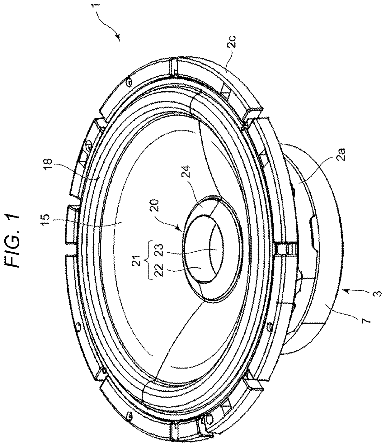
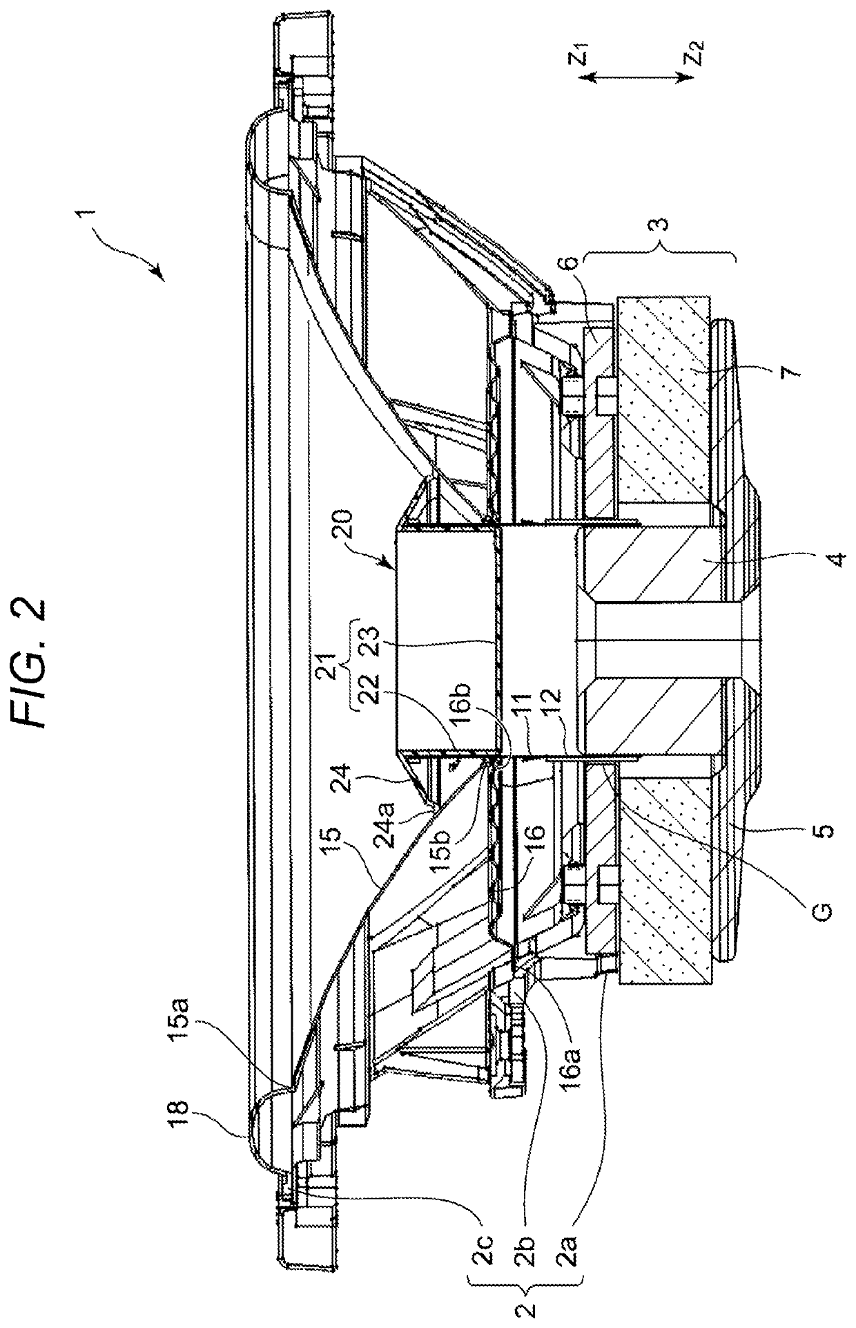
[0022]A speaker 1 of the invention illustrated in FIGS. 1 to 4 includes a frame portion 2. For example, the frame portion 2 is formed by die-casting light metal or is formed by press forming a steel plate. As illustrated in FIG. 2, the frame portion 2 includes a magnetic circuit portion support portion 2a, a damper support portion 2b, and a vibration plate support portion 2c. The frame portion 2 may be integrally formed as a whole or may be formed such that one of the magnetic circuit portion support portion 2a, the damper support portion 2b, and the vibration plate support portion 2c is formed separately from the other parts and these parts are combined and fixed to each other.

[0023]A magnetic circuit portion 3 is fixed to the magnetic circuit portion support portion 2a of the frame portion 2. As illustrated in FIG. 2, the magnetic circuit portion 3 includes a pole yoke 4 which is located at the center, a lower yoke 5 which is fixed to the lower side (the side of Z2) of the pole yo...

second embodiment

[0044]FIG. 7 is a half cross-sectional view illustrating a part of a counter drive type speaker 101 which is the invention.

[0045]Like the speaker 1 of the first embodiment, in the speaker 101 illustrated in FIG. 7, a direction in which an opening angle of a cone-shaped vibration plate is less than 180° is an upward direction and is directed in the Z1 direction.

[0046]In the counter drive type speaker 101, the magnetic circuit portion 3 is provided at the upper side (the side of Z1) and the magnetic circuit portion 3 is supported by the frame portion 2. The magnetic circuit portion 3 includes a pole yoke 4, an upper yoke 5a, and two opposing yokes 6a and 6b. The magnet 7 is fixed between the pole yoke 4 and the opposing yoke 6a, and the magnetic gap G is formed in the opposing portion between the yoke 6a and the yoke 6b. The voice coil 12 is wound on the bobbin 11 at the upper side, and the voice coil 12 is located inside the magnetic gap G.

[0047]The inner peripheral edge 15b of the v...


PUM


Abstract

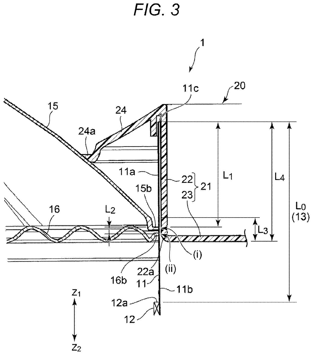
A cap member is attached to an opening end portion of a bobbin on which a voice coil is wound. The cap member includes a bobbin reinforcement portion including a cylindrical portion and a bottom surface portion. The cylindrical portion opposes an inner surface of the bobbin, and the cylindrical portion and the inner surface of the bobbin are fixed to each other in at least a vibration plate fixed portion and a damper member fixed portion.

Description

RELATED APPLICATION[0001]The present application claims priority to Japanese Patent Application Number 2017-109642, filed Jun. 2, 2017, the entirety of which is hereby incorporated by reference.BACKGROUND1. Field of the Invention[0002]The present invention relates to a speaker in which an inner peripheral edge of a vibration plate is fixed to a bobbin having a voice coil wound thereon, and the bobbin and the vibration plate are driven by a current flowing in the voice coil and a magnetic field of a magnetic circuit portion.2. Description of the Related Art[0003]In a structure of a conventional speaker, a voice coil is wound on a bobbin and magnetic energy of a magnetic circuit portion is transmitted to the voice coil so that the magnetic energy is converted into kinetic energy of the voice coil and the bobbin. Further, a vibration is transmitted from the bobbin to a vibration plate, and sound energy is emitted into a space from the vibration plate. In this speaker, when the rigidity...

Claims


Application Information

Patent Timeline
Patent Type & Authority Patents(United States)
IPC IPC(8): H04R9/06H04R7/18H04R7/12H04R9/02H04R1/28H04R9/04H04R31/00
CPCH04R9/06H04R1/288H04R7/127H04R7/18H04R9/025H04R7/12H04R9/043H04R2400/11H04R31/006
Inventor YAMAGAMI, MASARU
Owner ALPINE ELECTRONICS INC
Learn More