Oscillator with pulse-edge tuning

a technology of oscillator and pulse edge, applied in the field of oscillators, can solve problems such as mismatches in amplitude, phase and delay, and achieve the effects of improving accuracy, reducing noise, and improving accuracy

Active Publication Date: 2019-12-17
TEXAS INSTR INC
View PDF2 Cites 1 Cited by
  • Summary
  • Abstract
  • Description
  • Claims
  • Application Information

AI Technical Summary

Problems solved by technology

IQ mismatch can be errors in amplitude, phase and delay.

Method used


Image

  • Oscillator with pulse-edge tuning
  • Oscillator with pulse-edge tuning
  • Oscillator with pulse-edge tuning

Examples


Embodiment Construction

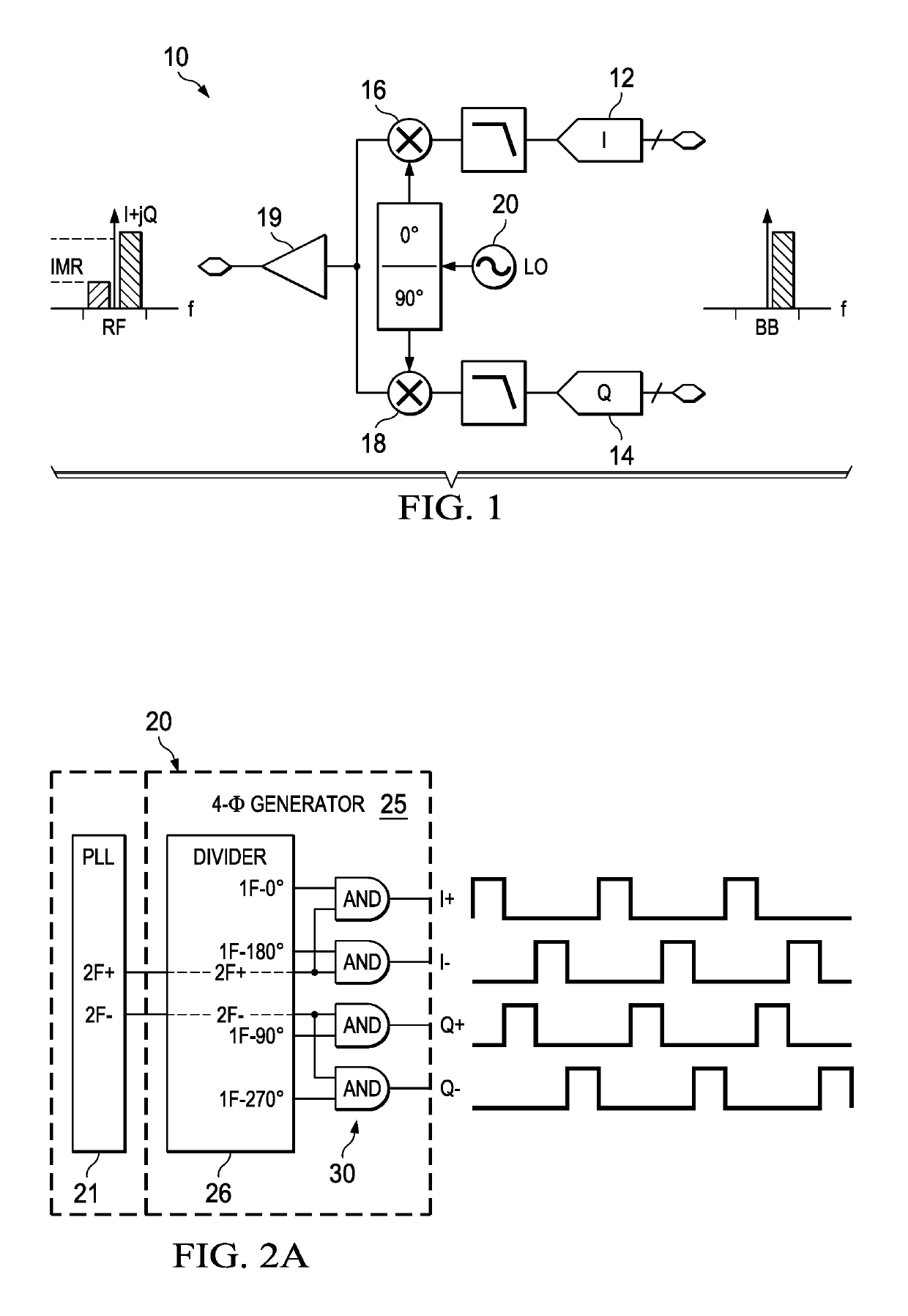
[0017]This Description and the Drawings constitute a Disclosure for an oscillator with pulse-edge tuning, including describing example embodiments, and illustrating various technical features and advantages. An example application is for implementing a local oscillator (LO) design for direct conversion RF TX / RX transceiver systems with LO-driven upconversion / downconversion in the transmit / receive signal chains.

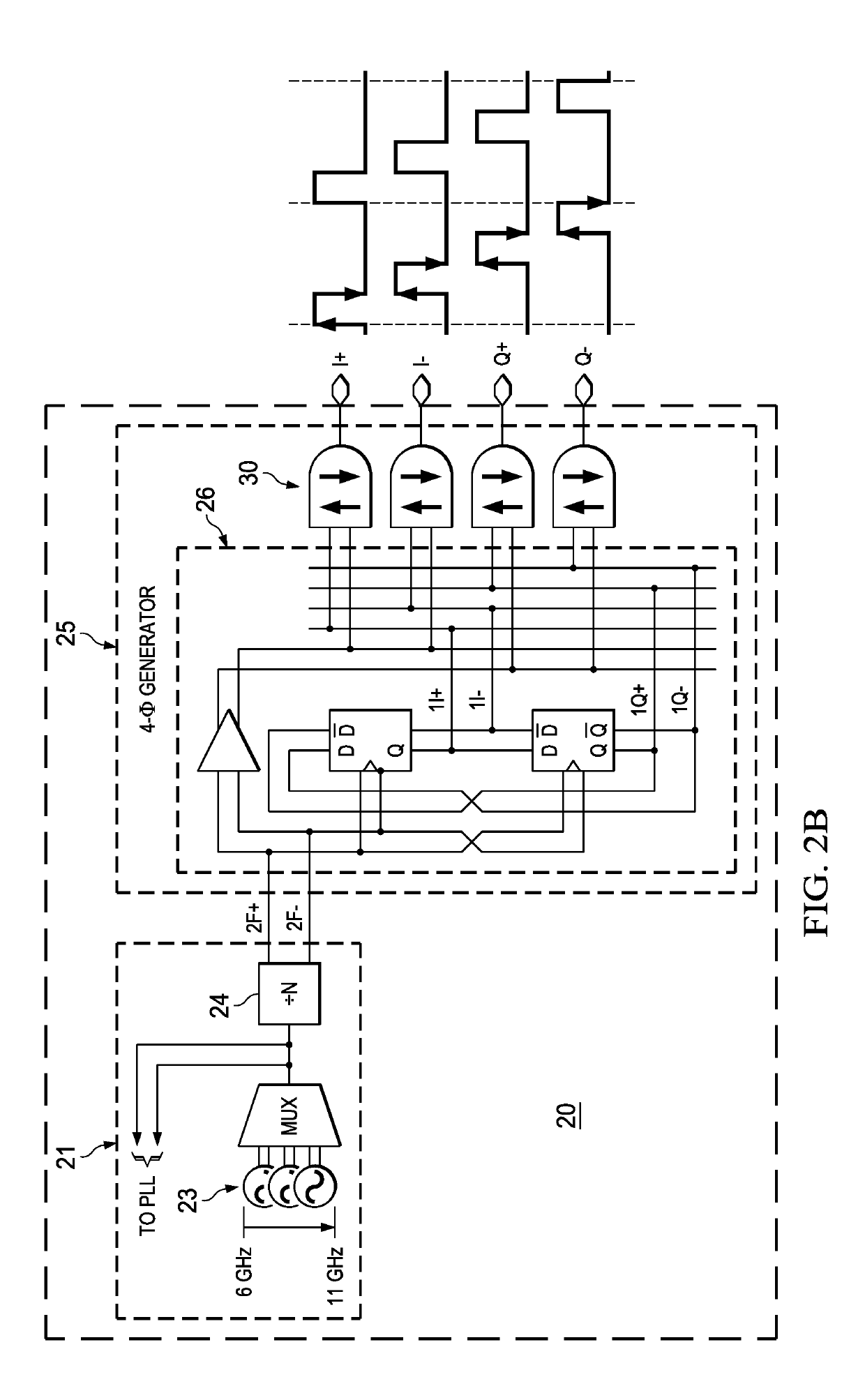
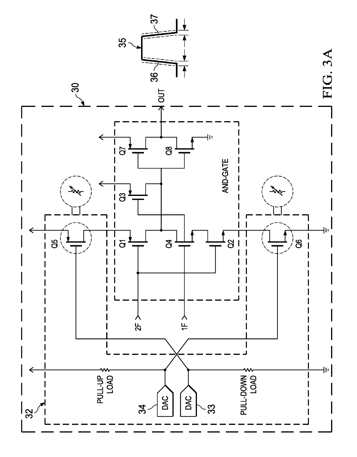
[0018]In brief overview an oscillator architecture with pulse-edge tuning. The oscillator includes a signal generator generating at least two signal frequencies, and a logic circuit (such as an AND gate) that combines the signal frequencies to generate a corresponding oscillator signal. The logic circuit includes a pull-up PMOS transistor coupled to a high rail, and a pull-down NMOS transistor coupled to a low rail. Duty cycle tuning / correction circuitry includes high and low side tuning FETs: a high-side tuning PMOS transistor is coupled between the high rail and a source ter...


PUM


Abstract

An oscillator architecture with pulse-edge tuning to control the pulse rising and falling edges (such as for duty cycle correction), including a signal generator with a pull-up PMOS transistor coupled to a high rail, and a pull-down NMOS transistor coupled to a low rail. Pulse-edge tuning circuitry includes a high-side tuning PMOS transistor between the high rail and a source terminal of the pull-up PMOS transistor, and a low-side tuning NMOS transistor between the low rail and a source terminal of the pull-down NMOS transistor. Both tuning FETs are controlled for operation as a variable resistor by respective high-side and low-side DACs to provide tuning control signals to the tuning FETs. In an example application, the oscillator design is adapted for a direct conversion RF signal chain (TX and / or RX) including an I-Path and a Q-Path: the signal generator generates ±I and ±Q differential signal frequencies.

Description

CROSS-REFERENCE TO RELATED APPLICATIONS[0001]Priority is claimed under 37 CFR 1.78 and 35 USC 119(e) to U.S. Provisional Application 62 / 279,191, filed Jan. 15, 2016), which is incorporated by reference.BACKGROUND[0002]Technical Field.[0003]This Patent Disclosure relates generally to oscillators, such local oscillators for use in direct conversion RF transmit / receive.[0004]Related Art[0005]Wireless direct conversion architecture use direct RF upconversion (TX signal chain) and / or downconversion (RX signal chain), eliminating conversion at an intermediate frequency (IF). Direct conversion architectures encompass zero and low IF designs, both commonly referred to as zero IF.[0006]Direct conversion (zero IF) architectures commonly use quadrature (IQ) signal conversion (modulation / demodulation), and digital filtering. FIG. 1 functionally illustrates a direct conversion transceiver 10 including I and Q signal paths. For the TX signal path, a digital baseband (BB) signal is input to I and ...

Claims


Application Information

Patent Timeline
Patent Type & Authority Patents(United States)
IPC IPC(8): H04L27/00H03K5/156H03M1/66H03B5/24H03L7/099H04B1/30H03B27/00H03H17/08H03H11/20H03B19/14
CPCH03B19/14H04L27/0014H03H17/08H03B5/24H03L7/099H03B27/00H03H11/20H03K5/1565H04B1/30H03B2201/0208H03M1/661
Inventor LITMANEN, PETTERI MATTIKLEMMER, NIKOLAUS
Owner TEXAS INSTR INC
Why Eureka
Try Eureka