
Combined wind and solar power generating system

a combined wind and solar power generation and power generation technology, applied in the field of electric generating and storage systems, can solve the problems of ineffective systems offering a well-integrated approach, system variability has been a problem, and the system is not well integrated with each other, so as to improve the dispatchability of the system, facilitate load sharing, and boost the energy conversion capability of solar energy collectors

Active Publication Date: 2019-12-24
SOLAR WIND RELIANCE INITIATIVES SWRI
View PDF41 Cites 0 Cited by
  • Summary
  • Abstract
  • Description
  • Claims
  • Application Information

AI Technical Summary

Benefits of technology

The system achieves higher power generation per unit area, improves induction generator efficiency, and enables effective operation at low wind speeds, enhancing flexibility and dispatchability of energy production.

Problems solved by technology

While solar energy and wind energy solutions both have well-established benefits in regards to carbon dioxide emission reduction, the variability of electricity generated from these devices has been a problematic concern for governments and other organizations charged with making electricity generation infrastructure decisions to balance electricity demand with the supply availability.
However, wind energy systems and solar energy systems currently in use tend to be separate.
However, these systems tend not to be well integrated with each other and tend to operate as if they were stand-alone units just sharing the same real estate.
To date, there do not appear to be any effective systems offering a well-integrated approach towards combining the capture of both wind and solar energy.

Method used


Image

  • Combined wind and solar power generating system
  • Combined wind and solar power generating system
  • Combined wind and solar power generating system

Examples


Embodiment Construction

Overview

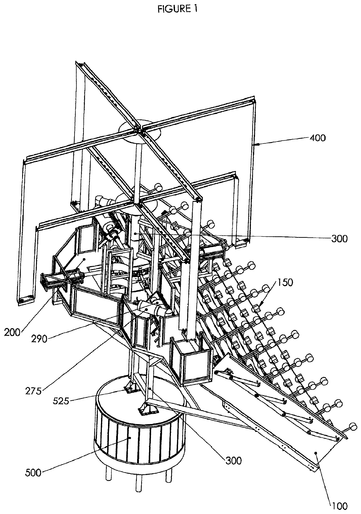
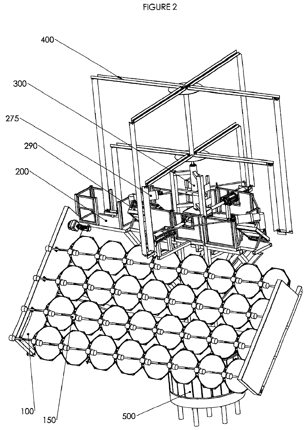
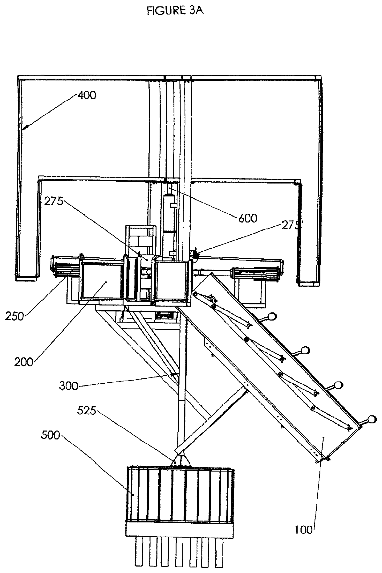
[0088]FIGS. 1 to 3E show the overall system. The solar collection array 100 is supported structurally by the main mast and frame assembly 300. Concentrated solar energy is redirected to heat engine storage compartments 290,290′, which act as heat sources for the heat engine 250, mounted on the main maintenance platform assembly 200. Efficiency of the heat engine is significantly increased by regenerators 275,275′ incorporated into the heat engine design.

[0089]The main mast and frame assembly 300 also provides structural support for the vertical axis wind turbine assembly (windmill arm and blade assembly) 400. The windmill arm and blade assembly rotate on the main vertical driveshaft 600. Structural moment and axial support of the main mast and frame assembly is provided by the rotator baseplate 525. Vertical axis or azimuth control for the entire assembly is provided by the base rotator assembly 500 which supports the rotator baseplate 525.

[0090]Electricity is produced from ...


PUM


Abstract

An integrated wind and solar solution is provided, including a solar energy collection assembly (100) and a vertical axis wind turbine (400), combined to provide an integrated power output. In preferred embodiments, the vertical axis wind turbine is positioned above the solar energy collection assembly. Concentrating solar mirror collectors (116) are used to direct sunlight to a heat engine (250), which converts the collected heat energy into rotary motion. Rotary motion from the heat engine and from the vertical axis wind turbine preferably are on the same rotating axis (600), to facilitate load sharing between these two sources. A dual axis azimuth-altitude solar panel alignment tracking system is used in order to boost the energy conversion capability of the solar energy collectors.

Description

BACKGROUND OF THE INVENTION[0001]This invention relates to an electrical generating and storage system which uses both wind and solar energy to produce electricity.[0002]In recent years, as the need for green technology solutions has become more apparent, electricity generating system installations have gone through a dramatic evolution away from carbon-based industrial generating systems towards solar energy and wind energy solutions. While solar energy and wind energy solutions both have well-established benefits in regards to carbon dioxide emission reduction, the variability of electricity generated from these devices has been a problematic concern for governments and other organizations charged with making electricity generation infrastructure decisions to balance electricity demand with the supply availability. An important concept in this context is “dispatchability”. Dispatchable energy sources are energy resources that can be ramped up or shut down in a short amount of time...

Claims


Application Information

Patent Timeline
Patent Type & Authority Patents(United States)
IPC IPC(8): F02D25/00H02S10/12F02G1/057F24S10/90F03D9/25F02G1/043F24S60/00F02G1/044F24S30/452H02S20/32F24S20/20F24S23/70F24S30/00F24S10/95F24S23/71
CPCH02S20/32F24S10/90F02G1/043F24S60/00F02G1/057F24S30/452F02G1/044F03D9/25F24S23/70H02S10/12F24S20/20F05B2240/214F02G2244/12F24S2030/131F24S2023/832F24S2023/837F24S2030/137F02G2254/30F24S2030/136H02S40/44F02G2243/30F02G2244/06Y02E10/60Y02E10/47F24S23/71F24S23/74F24S23/79Y02E10/46F24S10/95Y02E10/50Y02E10/72Y02E10/44Y02E10/74Y02E10/40
Inventor ARMSTRONG, ROSS D.
Owner SOLAR WIND RELIANCE INITIATIVES SWRI
Learn More