Contactless distance sensor and method for carrying out a contactless distance measurement
a technology of contactless distance sensor and distance measurement, which is applied in distance measurement, surveying and navigation, instruments, etc., can solve the problems of user inability to modify the behavior of the sensor, the user is usually not able to directly measure the time taken by light to “come back”, and the solution is not optimal, so as to achieve high precision
Active Publication Date: 2019-12-31
DATALOGIC IP TECH
View PDF14 Cites 0 Cited by
- Summary
- Abstract
- Description
- Claims
- Application Information
AI Technical Summary
Benefits of technology
The system provides improved precision and faster response times for both static and dynamic measurements without manual intervention, ensuring accurate distance measurement and reducing computational load and user supervision costs.
Problems solved by technology
However, the time taken by light to “come back” is not generally measured directly.
The user usually is not able to modify the behavior of the sensor, unless by interrupting the measurement and resetting the operating mode.
However, the Applicant has noted how this solution is not optimal, in particular for the measurement of moving target objects.
Such a technique is also slow and imprecise for a moving object: for dynamic measurements giving priority to one characteristic could automatically worsen the other and this is often not tolerated; in other words, giving priority to precision makes the device slow, giving priority to response speed, for example emitting the last measurement value acquired in the case of moving objects as an estimation of the distance, makes the device imprecise.
Moreover, the fact that the operating mode of the sensor used to carry out the measurement, for which the output value of the sensor is for example either the average of N measurements, or the last measurement obtained, depends on the choice of the user, can make the measurement inaccurate, in the case of an incorrect choice among the operating modes available or a change in the measurement situation from a stationary object to a moving object, or vice-versa, without the user realizing.
Moreover, the fact that the user must make the choice manually requires continuous supervision of the sensor by the user, wasting time and money.
Method used
View moreImage
Smart ImageViewing Examples
Examples
example
[0240]A time of flight sensor was selected and the following values were set:
[0241]M=3
[0242]NMAX=32
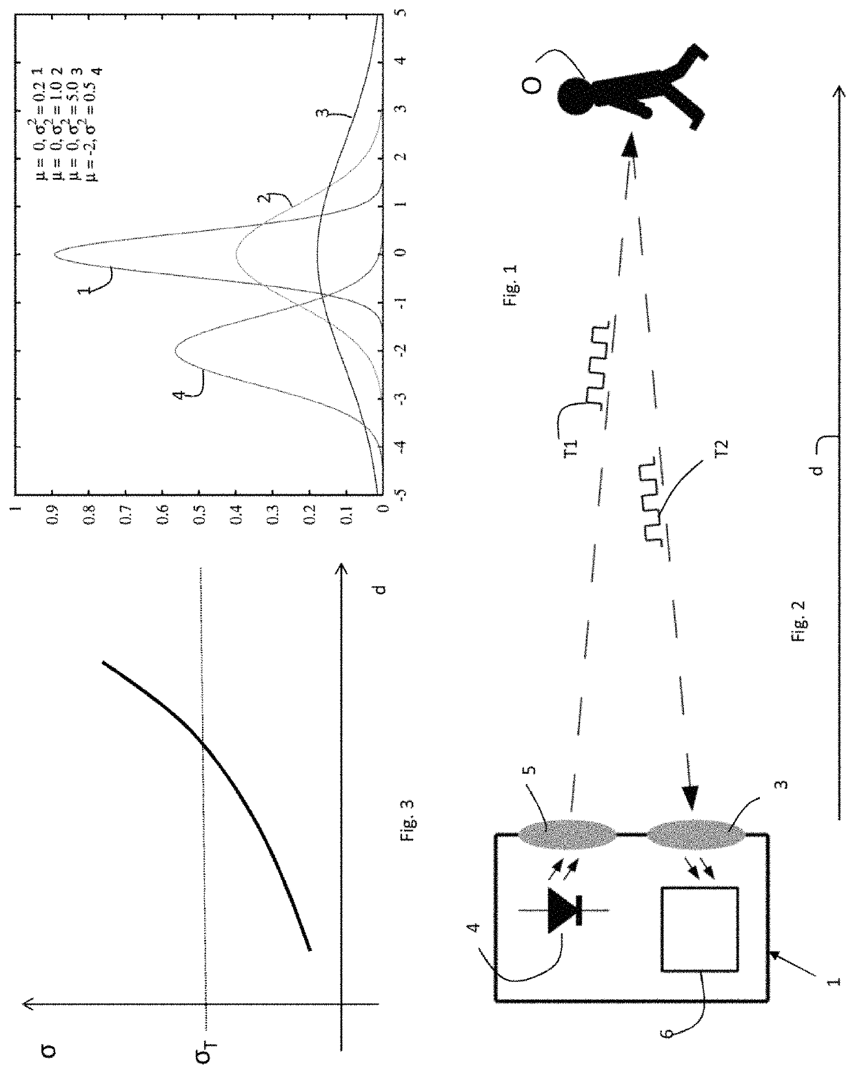
[0243]σN(d=20 m)=1.6 mm=σT is the standard deviation target,
[0244]the following formula is thus used N(d)=[σ(d) / σT]{circumflex over ( )}2
[0245]from which
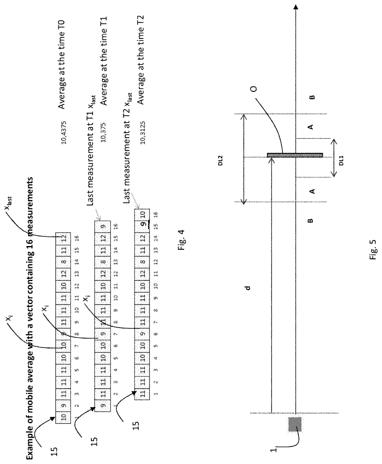
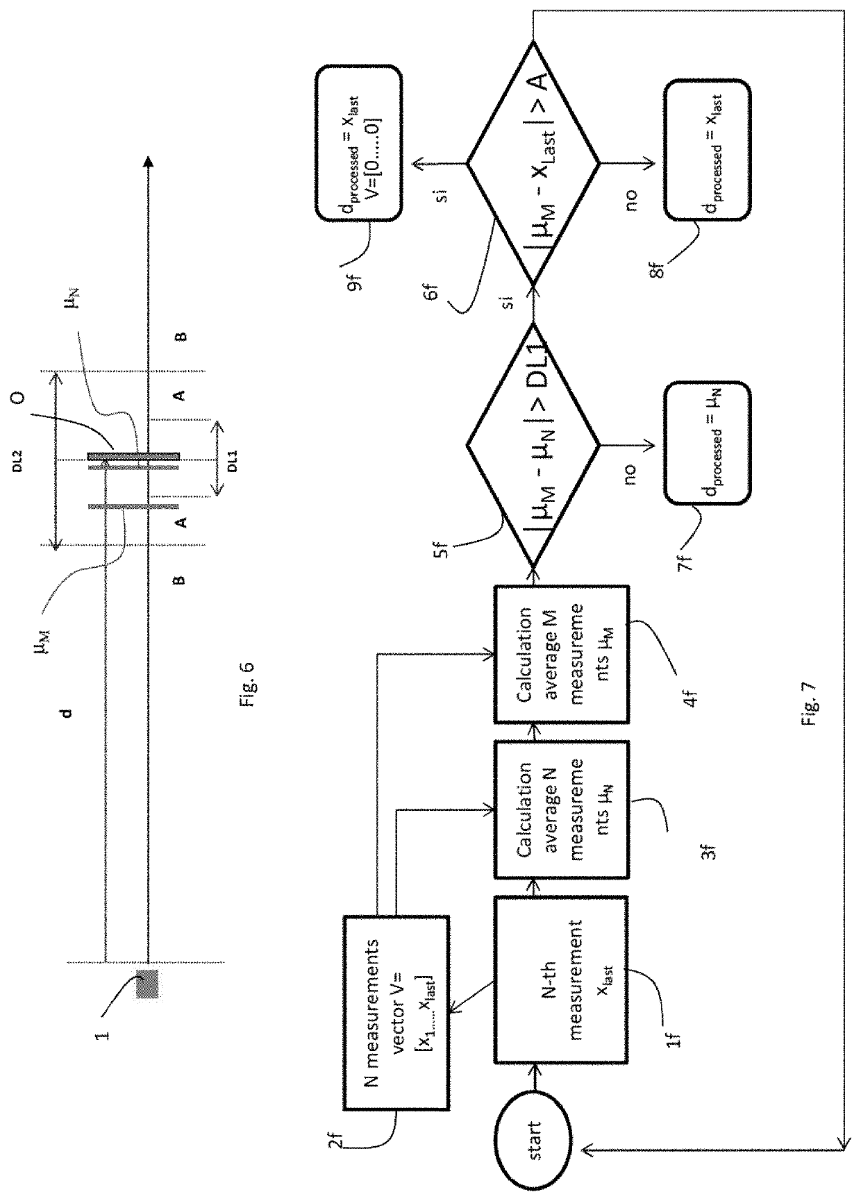
[0246]DL1=±5 mm; DL2=±20 mm per d=0.2 m
Login to View More PUM
 Abstract
The present invention relates to a distance sensor suitable for calculating a processed distance of a target object without contact, including: a contactless measuring circuit suitable for emitting an output signal proportional to the distance of said target object for a plurality of time intervals, so as to obtain a plurality of measurements of the distance of said target object without contact; a first processor circuit suitable for processing said output signals coming from said measuring circuit, so as to calculate a first average distance from said target object based on the average of N distance measurements in output coming from said measuring circuit, said N measurements being consecutive in time and including the last distance measurement emitted by said measuring circuit; a second processor circuit suitable for processing said output signals coming from said measuring circuit, so as to calculate a second average distance from said target object based on the average of M distance measurements in output coming from said measuring circuit, said M measurements being a subset of said N measurements with M<N, consecutive in time and including the last distance measurement emitted by said measuring circuit; a first comparator circuit suitable for calculating a first difference between a value function of said first average distance and a value function of said second average distance; and a third processor circuit suitable for comparing said first difference with a first threshold and for emitting in output a processed distance value, said processed distance value being equal to a value function of said first average distance if said first difference is less than or equal to said first threshold, or being equal to a value function of said last distance measurement emitted by said measuring circuit otherwise. Furthermore, the invention relates to an operating method of said sensor.
Description
BACKGROUND[0001]Technical Field[0002]The present invention relates to a contactless distance sensor having improved accuracy and precision, in particular in measuring the distance of moving target objects. Furthermore, the invention relates to an operating method of such a sensor.[0003]Description of the Related Art[0004]Devices or sensors for measuring the distance of objects are known as “contactless” when, in order to carry out the aforementioned measurement, there is no physical contact between the object for which it is wished to measure the distance and the sensor. This type of sensor is generally used in various applications from process automation to quality control in test beds, pneumatic cylinders, in engineering, etc. A sub-class of these sensors is called proximity sensors, usually being able to detect the presence of objects in the immediate vicinity of the “sensitive side” of the sensor itself, of course also in this case without there being any actual physical contact...
Claims
Login to View More Application Information
Patent Timeline
 Patent Type & Authority Patents(United States)
IPC IPC(8): G01S13/00G01B21/16G01C3/02G01S17/10G01S17/50G01S7/48
CPCG01B21/16G01C3/02G01S17/50G01S7/4808G01S17/10
Inventor CANI, SALVATORE VALERIOLORENZONI, ENRICO
Owner DATALOGIC IP TECH
Features
- R&D
- Intellectual Property
- Life Sciences
- Materials
- Tech Scout
- Unparalleled Data Quality
- Higher Quality Content
- 60% Fewer Hallucinations
Learn More Browse by: Latest US Patents, China's latest patents, Technical Efficacy Thesaurus, Application Domain, Technology Topic, Popular Technical Reports.
© 2025 PatSnap. All rights reserved.Legal|Privacy policy|Modern Slavery Act Transparency Statement|Sitemap|About US| Contact US: help@patsnap.com


