Mini-severing and back-off tool with pressure balanced explosives

a technology of explosives and minisevering, which is applied in the direction of drilling casings, drilling pipes, and accessories of wells, etc., can solve the problems of pipe string occasionally being tightly stuck in a well, wall collapse for hundreds or even thousands of feet, and it is impossible to remove pipe string from the well or, in most cases, even rotate pipe string, so as to prevent contamination of booster explosives

Active Publication Date: 2020-01-21
W T BELL INT INC
View PDF11 Cites 0 Cited by
  • Summary
  • Abstract
  • Description
  • Claims
  • Application Information

AI Technical Summary

Benefits of technology

[0022]In an embodiment, the mini-severing and back-off tool can further comprise a fluid barrier disposed between the booster explosive and the plurality of explosive pellets. In an embodiment of the back-off tool, O-rings or other sealing members can be used for sealing between the detonator and the initiation housing to prevent potential contamination from well fluid and other sources.
[0026]In an embodiment, the method of releasing a threaded pipe joint within a pipe string can include the step of providing a fluid barrier between the booster explosive and the plurality of explosive pellets to prevent contamination of the booster explosive.
[0031]In an embodiment, the method can further comprise the step of providing a fluid barrier between the booster explosive and the plurality of explosive pellets to prevent contamination from potential well fluids or other sources.
[0034]In an embodiment, the back-off tool can further comprise a fluid barrier disposed between the detonator and at least one of the plurality of explosive pellets. In an embodiment, O-rings or other elastomeric sealing members can be used to seal between the firing head and the initiation housing to prevent contamination of the booster explosive from potential well fluids or other contaminating sources.

Problems solved by technology

In the course of downhole operations, such pipe strings occasionally become tightly stuck in a well.
Such a wall collapse may occur for hundreds or even thousands of feet along the borehole length.
In such an event, it is impossible to withdraw the pipe string from the borehole or, in most cases, even rotate the pipe string.
However, simply reversing the rotation of the pipe string will not necessarily separate the string at the first screwed joint above the seizure.
As additional pipe sections are added to a pipe string, the earlier assembled joints become tighter and more difficult to unthread or decouple.
Moreover, it is along the drill collar portion of the drill string that a formation seizure is most likely to occur.
However, as discussed below, these traditional methods encounter serious functional and reliability issues when used at great depths, particularly where the environmental conditions include high temperatures and / or high pressures.
(400° F.) or greater and the pressures may be several thousand pounds per square inch, the prior art methods and apparatus encounter serious functional and reliability issues.
For example, high pressures tend to decrease the explosive detonation sensitivity and suppress the shock intensity of an explosion, thus causing a complete lack of function or a diminished function of the explosives taught by the prior art methods and apparatus.
In addition, high temperatures tend to reduce the energy of the explosive, thus causing a lack of function or a diminished function with regard to the prior art methods and apparatus.
However, detonation cord is largely limited to distribution rates of 21 grams per meter (100 grains per foot) of explosive length.
Therefore, while the distributed weight value of detonation cord may be increased by detonating multiple parallel cords simultaneously, this technique is largely limited to about a maximum of fourteen (14) detonation cords.
As such, existing methods and apparatus cannot perform successfully at such great depths.

Method used


Image

  • Mini-severing and back-off tool with pressure balanced explosives
  • Mini-severing and back-off tool with pressure balanced explosives
  • Mini-severing and back-off tool with pressure balanced explosives

Examples


Embodiment Construction

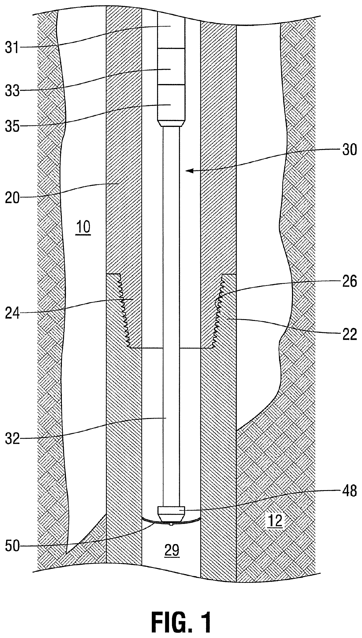
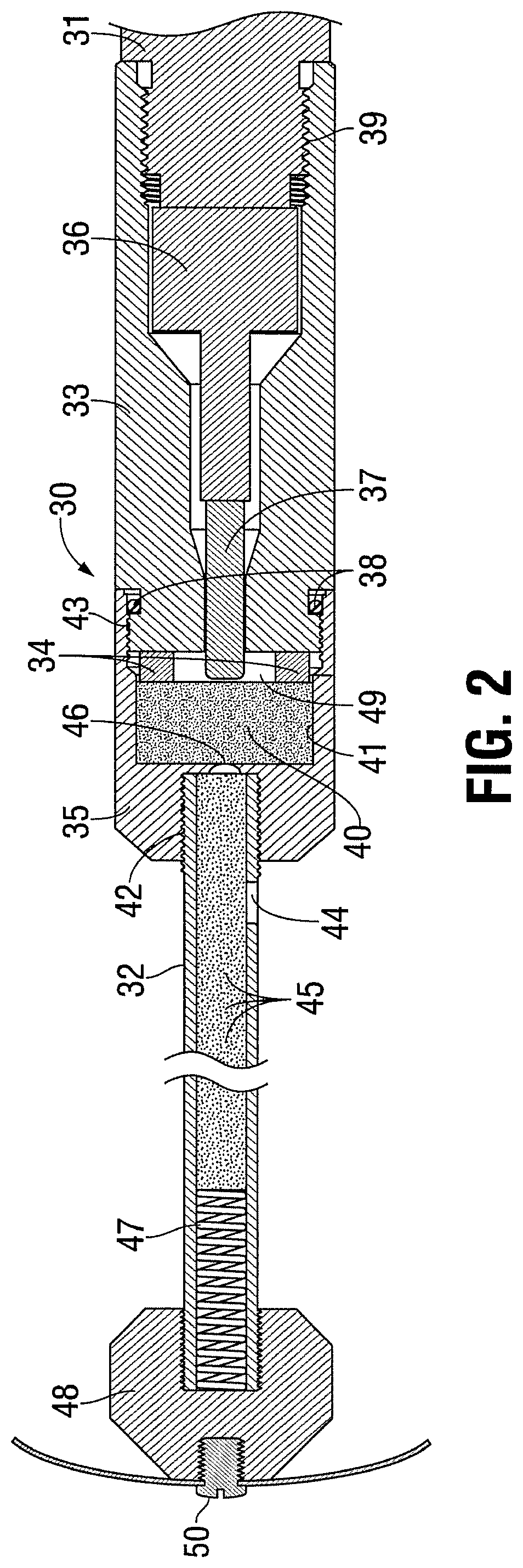
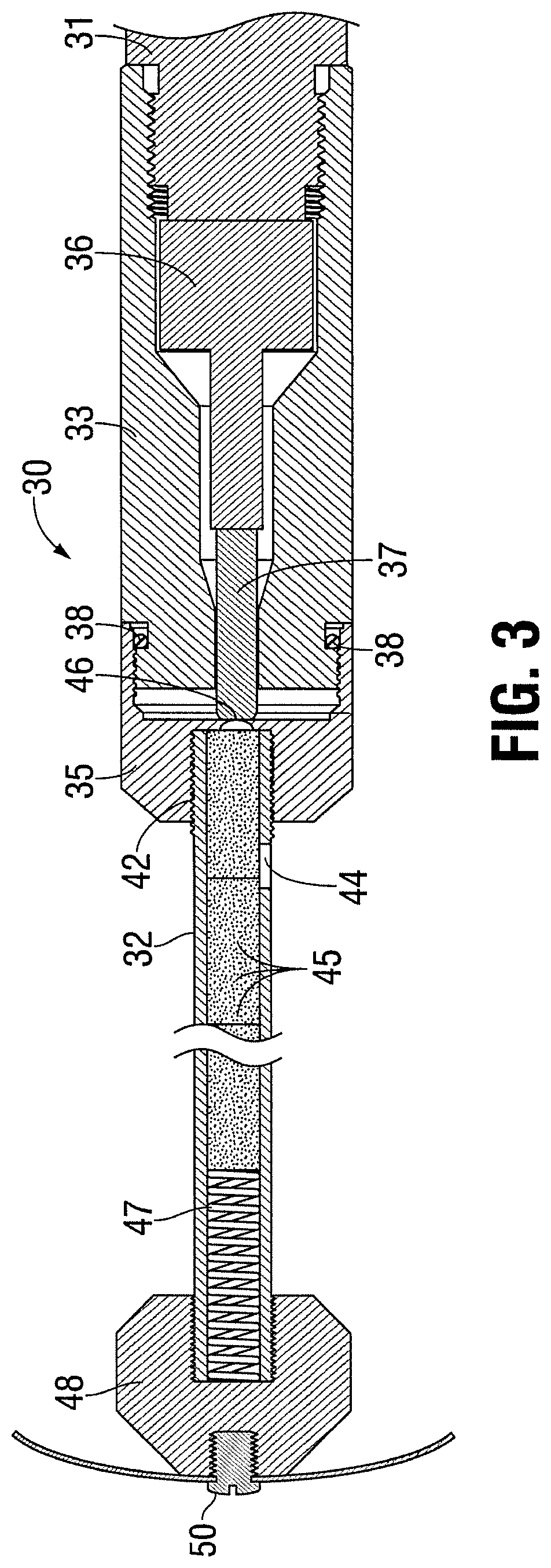
[0043]Before explaining selected embodiments of the present invention in detail, it is to be understood that the present invention is not limited to the particular embodiments described herein and that the present invention can be practiced or carried out in various ways. As used herein, the terms “up” and “down”, “upper” and “lower”, “upwardly” and downwardly”, “upstream” and “downstream”; “above” and “below”; and other like terms, indicating relative positions above or below a given point or element, are used in this description to more clearly describe some embodiments of the invention. However, when applied to equipment and methods for use in wells that are deviated or horizontal, such terms may refer to a left to right, right to left, or other relationship as appropriate. Moreover, in the specification and appended claims, the terms “pipe”, “tube”, “tubular”, “casing”, “liner” and / or “other tubular goods” are to be interpreted and defined generically to mean any and all of such...


PUM


Abstract

A “mini-severing and back-off” tool includes a tubular magazine for a column of explosive pellets that are sized in diameter to provide a predetermined weight of explosive per unit column length. The tubular wall is vented at prescribed intervals for fluid pressure equalization between the internal bore of the tubular and the fluid pressure around the outside of the tubular. A fluid barrier is positioned between one end of the explosive pellet tubular and a detonator or an explosive booster provided to detonate the explosive pellet tubular. The explosive pellet tubular is positioned within the flow bore of a pipe string and adjacent to an intended pipe joint, and the explosive pellet tubular is detonated simultaneously with an application of torque on the pipe string, wherein the torque is applied in the thread release direction to disassemble the intended pipe joint.

Description

CROSS-REFERENCE TO RELATED APPLICATION[0001]The present application is a domestic application that claims priority to, and the benefit of, International Patent Cooperation Treaty (PCT) Application No. PCT / US2015 / 051033, filed on Sep. 18, 2015, and having a title of “Mini-Severing And Back-Off Tool With Pressure Balanced Explosives,” which is incorporated herein in its entirety.FIELD[0002]The present invention relates generally to equipment and processes for deep well drilling. More particularly, the invention is directed to methods and / or apparatuses comprising pressure balanced explosives and usable for decoupling or unthreading a specific drill pipe collar or casing joint from a downhole string of pipe.BACKGROUND[0003]Rotary drilling of deep wells for the production of fluid minerals, such as oil and gas, relies upon long assemblies of multiple pipe sections called “strings”. Each pipe unit or section of pipe for this purpose, normally, is in the order of nine to twelve meters (30...

Claims


Application Information

Patent Timeline
Patent Type & Authority Patents(United States)
IPC IPC(8): E21B29/02E21B17/06
CPCE21B29/02E21B31/1075
Inventor BELL, WILLIAM T.RAIRIGH, JAMES G.
Owner W T BELL INT INC
Why Eureka
Try Eureka