
Method of separating, identifying and characterizing cracks in 3D space

a three-dimensional space and crack technology, applied in the field of crack identification, can solve the problems of affecting the subsequently material strength, the observation cannot extract the two-dimensional (2d) characteristics of cracks on the observed surface, and encounters very technical difficulties

Active Publication Date: 2020-01-21
SUN YAT SEN UNIV
View PDF2 Cites 3 Cited by
  • Summary
  • Abstract
  • Description
  • Claims
  • Application Information

AI Technical Summary

Benefits of technology

The invention allows for the precise identification and characterization of cracks in complex crack networks. It does this by using a method that separates cracks from enclosed surfaces and restores the thickness and dimensions of the cracks after they have been broken. This provides important technical support for research into crack morphology, permeability, and mechanical response, as well as scaling up.

Problems solved by technology

Cracks are commonly developed in rocks (and other brittle materials), which are caused by forces and damage, and have significant effects on subsequently material strength.
These observations can only extract two-dimensional (2D) characteristics of cracks on the observed surface.
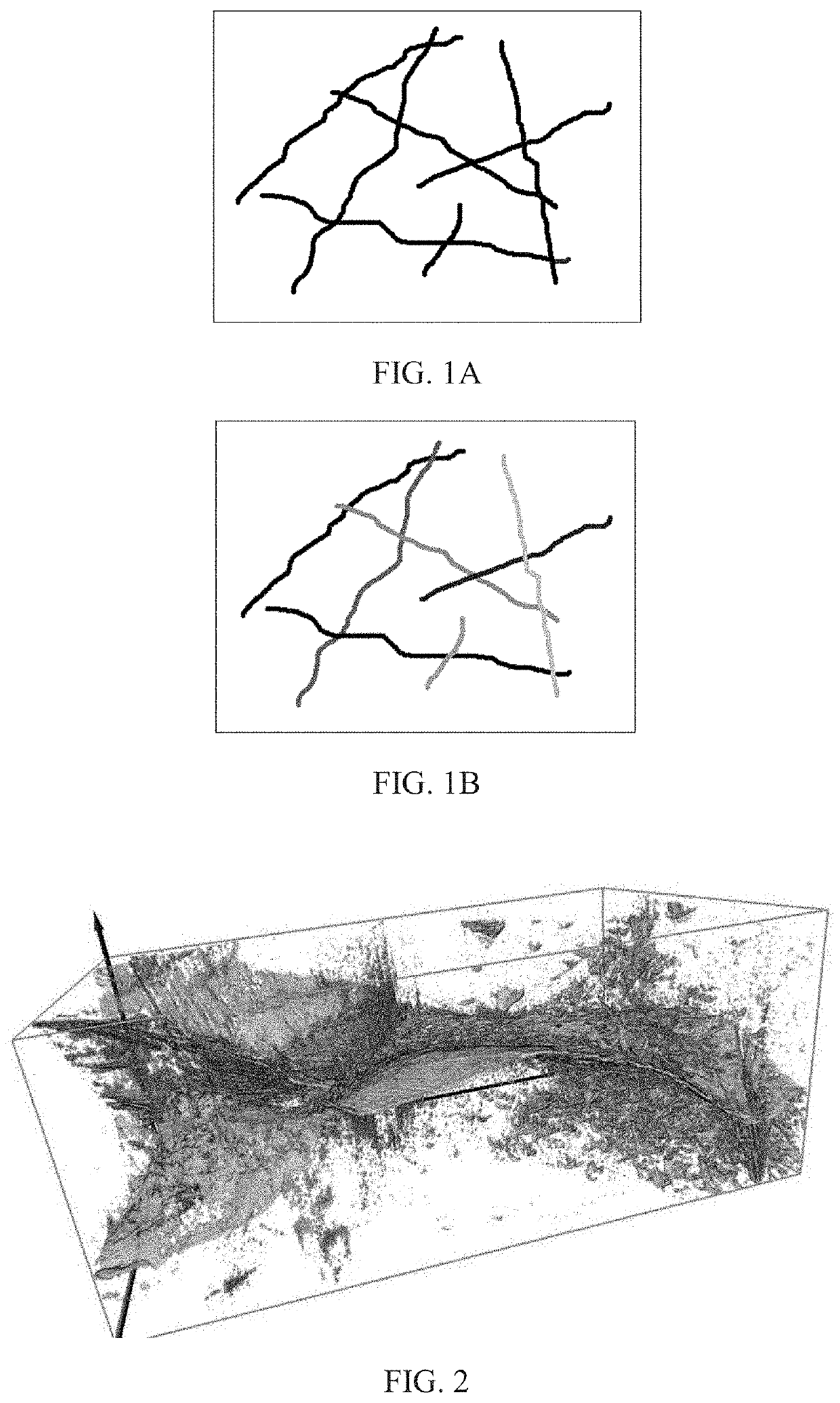
When the problem is extended to three dimensions, since the distribution and intersection of the cracks in the 3D space may be extremely complex, the separation and identification one by one of the individual cracks, which the characterization of the cracks firstly needs to achieve, encounters very technical difficulties.
From the complex 3D crack network shown in FIG. 2, it can be seen that the separation and identification of each of the individual cracks will be a huge challenge.
It is not applicable for a crack network in a general case (such as a very simple case: two intersecting cracks without reaching the boundary of the model).
The quantitative characterization of crack structures is difficult to develop because the separation and identification of the individual cracks fail to be achieved.

Method used


Image

  • Method of separating, identifying and characterizing cracks in 3D space
  • Method of separating, identifying and characterizing cracks in 3D space
  • Method of separating, identifying and characterizing cracks in 3D space

Examples


Embodiment Construction

[0065]The present invention is further described below in combination with the accompanied drawings, but implementations of the present invention are not limited hereto.

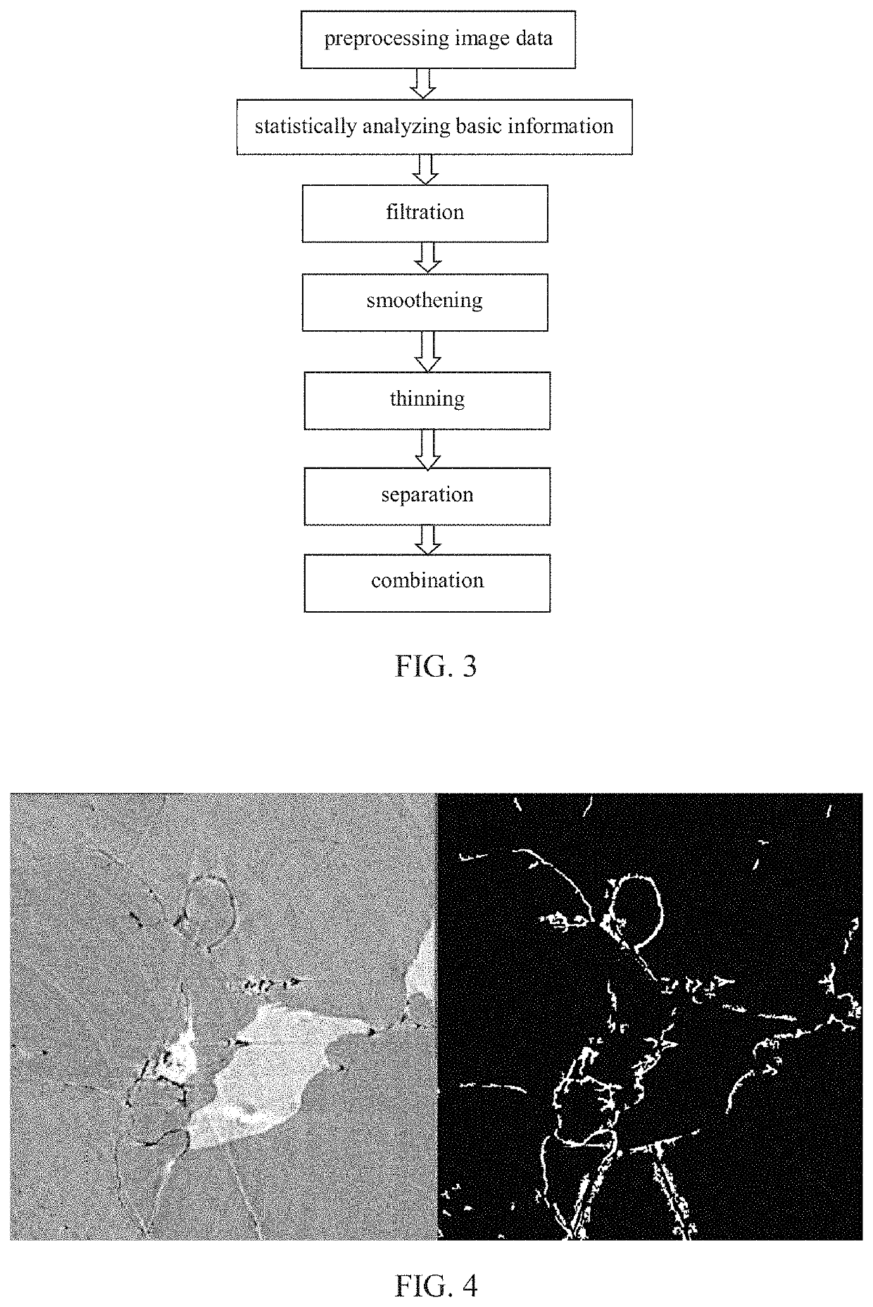
[0066]Micro-CT images are commonly asked for routine preprocessing, including smoothening, denoising, edge cutting, image segmentation (identification of crack or pore). Thus the actual work requires 7 steps, and there are 6 main steps after the image segmentation, as shown in FIG. 3, that is:

[0067]0) preprocessing digital image

[0068]1) statistically analyzing basic information: basic information of the digital image, such as porosity, connectivity, structure anisotropy, etc.

[0069]2) filtration: removing non-crack structure in the data, such as very small structures or structures with strong isotropic

[0070]3) smoothening: smoothening and mending the digital image

[0071]4) thinning: thinning the void structure into a certain thickness in a most narrow direction in three-dimensions

[0072]5) separation: separating interse...


PUM


Abstract

The present invention discloses a method of separating, identifying and characterizing cracks in rocks or other materials in three-dimensional (3D) space, which processes as follows to a volumetric digital image: 1) preprocessing digital image; 2) statistically analyzing basic information of the image including porosity, connectivity of each pore, and position, size, orientation and anisotropy of each pore-structure; 3) filtration: removing non-crack structures; 4) smoothening: smoothening and mending the image; 5) thinning: thinning the void structure into a thickness d (2 to 3 voxels recommended) in a direction with shortest extension; 6) separation: separating intersected cracks in a crack network by breaking the connections; 7) combination: combining those elongated cracks that are disconnected in the last step, and restoring cracks to the thickness before thinning, and eventually giving out the characterization of the cracks.

Description

CROSS-REFERENCE TO RELATED APPLICATION[0001]This application claims the priority benefit of China application serial no. 201610494280.5, filed on Jun. 27, 2016. The entirety of the above-mentioned patent application is hereby incorporated by reference herein and made a part of this specification.TECHNICAL FIELD[0002]The present invention relates to a field of crack identification, and more particularly, to a method of separating, identifying and characterizing intersected cracks in three-dimensional (3D) space.BACKGROUND[0003]Cracks are commonly developed in rocks (and other brittle materials), which are caused by forces and damage, and have significant effects on subsequently material strength. Meanwhile, the cracks play an important role in fluid migration (e.g. groundwater, oil and gas). Characterization or description of the cracks is the basis of the study of the relationships between mechanics, fluid mechanics and the geometry of cracks. Quantitative characterization of the cr...

Claims


Application Information

Patent Timeline
Patent Type & Authority Patents(United States)
IPC IPC(8): G06T7/00G06T7/60
CPCG06T7/60G06T7/0004G06T7/0002G06T2207/20036G06T2207/10081G06T2207/30184G01N2015/0846G01N15/088
Inventor LIU, JIEHUANG, JINCHENG
Owner SUN YAT SEN UNIV
Learn More