
System and method for real-time MRI-guided object navigation

a real-time mri-guided object and navigation system technology, applied in the field of real-time mri-guided object navigation system, can solve the problems of slowing down the overall procedure, slowing down the needle positioning procedure, and requiring a long repetition time tr, so as to facilitate the directional adjustment of the needle advancement

Active Publication Date: 2020-02-04
SIEMENS HEALTHCARE GMBH +1
View PDF3 Cites 0 Cited by
  • Summary
  • Abstract
  • Description
  • Claims
  • Application Information

AI Technical Summary

Benefits of technology

The patent describes a magnetic resonance imaging system and method for real-time MRI of objects inserted into biological tissue. The system uses a compressed sensing approach to obtain high-resolution images in real-time, which can guide the needle placement accurately. The method takes advantage of the known path of the object, the unchanging nature of images away from the path, and the limited difference between successive images to minimize the cost function. The improved spatial and temporal resolution of the MRI technique allows for a continuous adjustment of the insertion procedure to follow a predetermined trajectory in the tissue. The MRI system can generate sequences of gradient and RF pulses and display the generated images in real-time. Overall, the patented method and system can provide high-quality images in real-time to accurately guide the insertion of objects into biological tissue.

Problems solved by technology

However, T2-weighted imaging typically requires a long repetition time TR, and acquisition times for a single frame / image can be on the order of several seconds.
These higher-resolution verification datasets often have an acquisition time of 20 seconds or more, and thus slow down the needle positioning procedure.
The workflow interruptions needed to accurately verify needle positions during the advancement process slow down the overall procedure and impede a continuous insertion process.

Method used


Image

  • System and method for real-time MRI-guided object navigation
  • System and method for real-time MRI-guided object navigation
  • System and method for real-time MRI-guided object navigation

Examples


Embodiment Construction

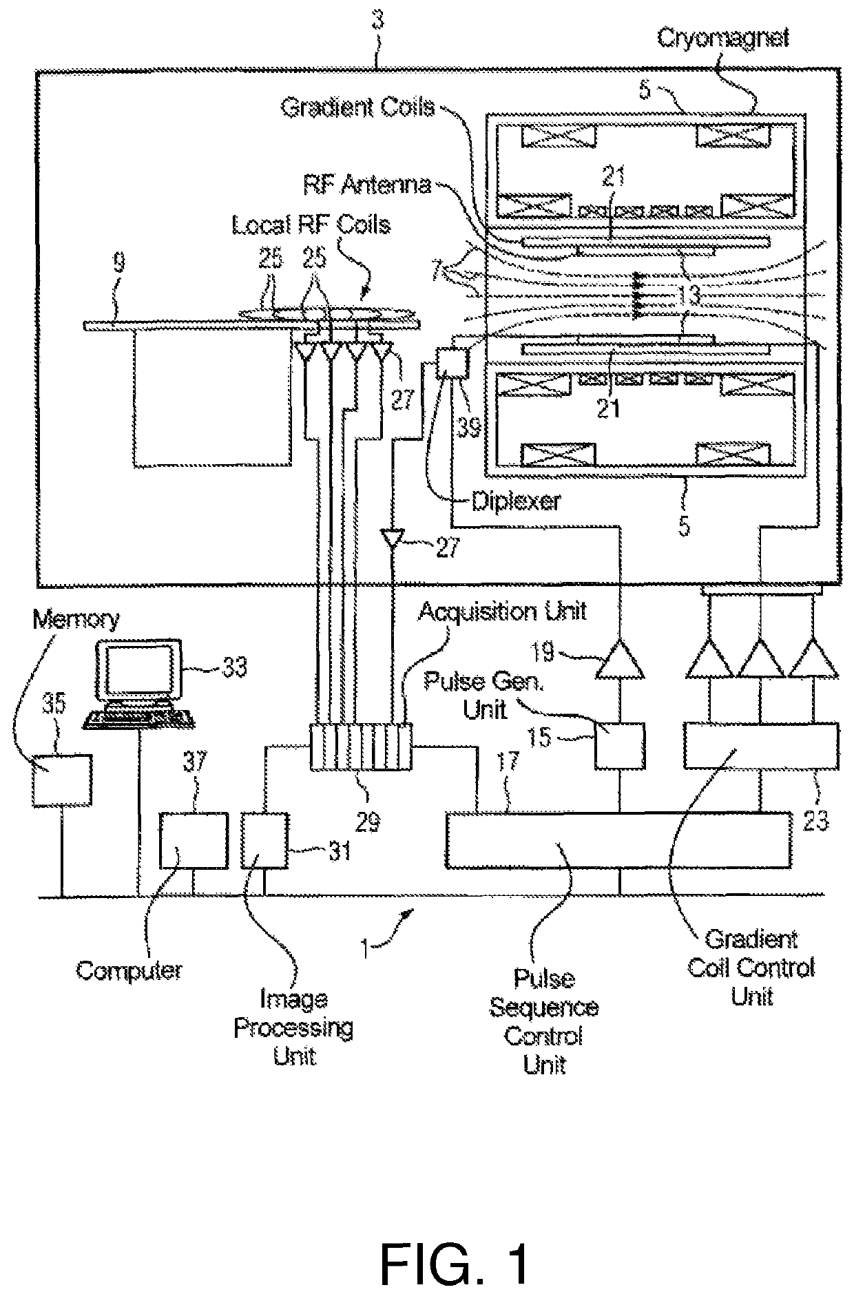
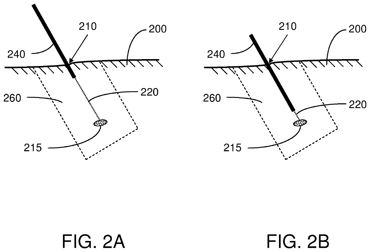
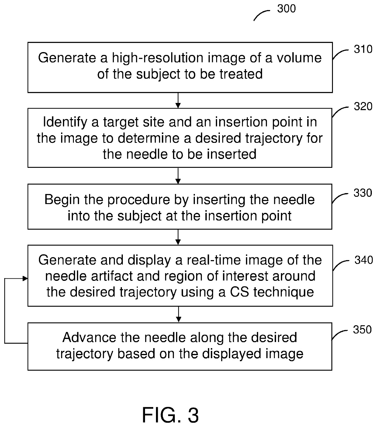
[0007]Exemplary embodiments of the present disclosure can provide magnetic resonance imaging systems and methods for real-time MRI of an object (such as a needle) while it is being inserted into biological tissue, using improved MRI techniques that can provide sufficiently high resolution images in real time to precisely guide the needle placement. The MRI techniques employ a compressed sensing approach that takes advantage of a pre-determined object path, known artifact effects associated with the object, the unchanging nature of images away from the object path, and the limited differences between successive images, where these factors are expressed as a cost function that can be minimized using the compressed sensing approach. The improvements in combined spatial and temporal resolution, as compared to conventional imaging techniques, facilitate an insertion procedure that can be continuously adjusted to accurately follow a predetermined trajectory in the tissue.

[0008]Certain emb...


PUM


Abstract

A magnetic resonance method and system are provided for magnetic resonance (MR) image-guided insertion of an object into a biological tissue along a predetermined trajectory. The trajectory provides a path between a starting point and a target site within the tissue. Sufficiently high resolution images can be generated in real time to precisely guide the needle placement. A compressed sensing approach is used to generate the images based on minimization of a cost function, where the cost function is based on the predetermined needle path, artifact effects associated with the needle, the negligible changes in the images away from the trajectory, and the limited differences between successive images. The improved combination of spatial and temporal resolution facilitates an insertion procedure that can be continuously adjusted to accurately follow a predetermined trajectory in the tissue, without interruptions to obtain verification images.

Description

STATEMENT REGARDING FEDERALLY SPONSORED RESEARCH[0001]The present invention was made with government support under National Institutes of Health Grant No. NIH R01 EB007829. The government has certain rights in the invention.FIELD OF THE DISCLOSURE[0002]The present disclosure relates to a system and method for tracking a moving needle or other object while it is being inserted into biological tissue, using improved magnetic resonance imaging (MRI) techniques that can provide sufficiently high resolution images in real time to precisely guide the needle placement. The MRI techniques employ a compressed sensing approach that takes advantage of the pre-determined needle path, known artifact effects associated with the needle, and the unchanging nature of images away from the needle path to provide images having improved resolution in real time, thereby avoiding the need to interrupt the needle advancement periodically to obtain slow high- resolution verification images.BACKGROUND INFORM...

Claims


Application Information

Patent Timeline
Patent Type & Authority Patents(United States)
IPC IPC(8): A61B5/055
CPCA61B5/055A61B5/0033G01R33/286G01R33/5611A61B2090/374A61B2034/107A61B5/0036
Inventor ROTHGANG, EVAHENGERER, ARNELAUER, LARSFRITZ, JANBOTTOMLEY, PAULGILSON, WESLEY DAVIDGRIMM, ROBERT
Owner SIEMENS HEALTHCARE GMBH
Learn More