Microdosing system

a microdosing system and microdosing technology, applied in the direction of liquid/fluent solid measurement, volume/mass flow by differential pressure, stationary measuring chambers, etc., can solve the problems of flow sensors, undesired drift behavior, and large and expensive known microdosing systems, so as to prevent free flow, prevent undesired backflow of fluid, and prevent undesired backflow

Active Publication Date: 2020-02-04
FRAUNHOFER GESELLSCHAFT ZUR FOERDERUNG DER ANGEWANDTEN FORSCHUNG EV
View PDF47 Cites 1 Cited by
  • Summary
  • Abstract
  • Description
  • Claims
  • Application Information

AI Technical Summary

Benefits of technology

[0028]In a further embodiment, the microdosing system can comprise a control means that is configured to compare the flow rate determined through the opening of the first flow sensor with a predetermined flow rate comparison value for controlling the micropump for so long until the flow rate determined through the opening of the first flow sensor is equal to or greater than the predetermined flow rate comparison value. In that way, the micropump can advantageously dispense a desired and predefined, respectively, amount of fluid. If an amount of discharge is necessitated that is greater than the amount to be dispensed with a single pump stroke, the control means can control the micropump until the desired amount is reached.
[0030]It is possible that the valve provided on the inlet side is arranged between the micropump and a flow sensor arranged on the inlet side or in flow direction prior to a flow sensor arranged on the inlet side, and that the valve provided on the outlet side is arranged between the micropump and the first flow sensor arranged on the outlet side or in flow direction after the first flow sensor arranged on the outlet side. These are particularly advantageous positions for arranging the blocking valves for preventing free flow.
[0031]It is possible that the first flow sensor is arranged in contact with the outlet of the micropump on the outlet side and at least in sections. In that way, there is a direct connection between the pump outlet and the flow sensor, at least in sections. In that way, the paths that the fluid to be dispensed has to cover between pump outlet and flow sensor can advantageously be kept short. Thus, the pump pressure can be transferred in an almost loss-less manner to the flow sensor.
[0032]According to an embodiment, the micropump can comprise a valve on the outlet side that is configured to close the outlet when the micropump sucks the fluid to be dispensed and that is configured to open the outlet when the micropump dispenses the fluid to be dispensed from the outlet. Such a valve prevents undesired backflow of the fluid to be dispensed and leakage flow in rearward direction. In that way, this valve allows the fluid to be dispensed to pass through the outlet valve in the pressure stroke of the pump. In the suction stroke of the pump, however, closing of the outlet is desired in order to be able to pump new fluid to be dispensed through the inlet into the pump chamber. Thus, this valve closes the outlet and prevents undesired backflow of the fluid to be dispensed through the outlet in the suction stroke of the micropump.
[0033]It is possible that the micropump comprises a valve on the inlet side that is configured to open the inlet when the micropump sucks the fluid to be dispensed and that is configured to close the inlet when the micropump dispenses the fluid to be dispensed from the outlet. This valve prevents undesired backflow of the fluid to be dispensed in the pressure stroke of the pump and a leakage flow in rearward direction, respectively, if, for example, the pressure on the outlet side is greater than the pressure on the inlet side. In that way, this valve allows the fluid to be dispensed to enter through the inlet valve in the suction stroke of the pump. However, in the pressure stoke of the pump, closing of the inlet is desired in order to be able to build up pressure in the pump chamber. Thus, this valve closes the inlet in the pressure stroke of the micropump and hence prevents undesired backflow of the fluid to be dispensed through the inlet. If, for example, when the pump is inactive, the pressure on the outlet side is higher than the pressure on the inlet side, this valve can prevent an undesired leakage flow in rearward direction, i.e., towards the inlet.
[0034]It is possible that the second flow sensor is arranged in contact with the inlet of the micropump, at least in sections. In that way, there is a direct connection between the pump inlet and the second flow sensor, at least in sections. Thus, the paths that the fluid to be dispensed has to cover between the second flow sensor and the pump inlet can advantageously be kept short.

Problems solved by technology

Known microdosing systems, however, are usually large and expensive.
Due to such stress induced during assembly, known pressure and flow sensors, respectively, show undesired drift behavior when the same are assembled in a conventional manner.
High-quality pressure and flow sensors, respectively, have to be assembled expensively in a stress-free manner for preventing the sensor drift, which, however, increases the costs.
Such stress-free mounting methods, however, are very expensive, which again prevents the usage of such microdosing chips in applications necessitating low production costs.
If, however, microdosing pumps and microdosing chips are combined with one another in a cost-effective production method, the sensor value of the microdosing chip will drift due to the above stated reasons, i.e., due to the stress induced during assembly, which prevents exact dosing of the microdosing system.
When the two values do not correspond, the microdosing system can conclude that an error has occurred, such as leakage of valves or a gas bubble in the pump chamber.
This would indicate that fluid leaks from the inlet which should, however, actually be closed in a fluid-tight manner during the pressure stroke of the pump.
Possible volume stroke differences indicate, for example, a measurement error.
Advantageously, only low or even no “fluidic capacitances” exist between micropump and voltage sensor, such as soft long plastic tubes or other elastic elements that would cause time delays until the flow comes to rest, since long soft tubes widen and in that way enlarge their volume.
In a static flow, the flow sensor cannot differentiate whether the opening is blocked.

Method used


Image

  • Microdosing system
  • Microdosing system
  • Microdosing system

Examples


Embodiment Construction

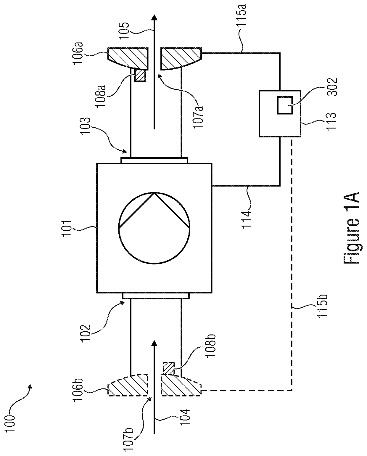
[0046]FIG. 1A shows an inventive microdosing system 100 for dosing an amount of fluid to be dispensed. The fluid to be dispensed can, for example, by a gas or a liquid. The fluid can have different rheologic characteristics. For example, the fluid can have a low viscosity. The fluid having a low viscosity can, for example, be a cream or a lotion. The fluid can comprise medically active ingredients. The fluid can, for example, also be a deodorant solution containing scents.

[0047]The micodosing system 100 comprises a micropump 101. The micropump 101 comprises an inlet 102 and an outlet 103.

[0048]The micropump 101 is configured to suck the fluid to be dispensed, indicated by the arrow 104, through the inlet 102. Further, the micropump 101 is configured to dispense at least part of the fluid indicated by the arrow 105 from the outlet 103.

[0049]The microdosing system 100 comprises a first flow sensor 106a, 106b. The first flow sensor 106a is arranged on the outlet side, i.e., the same is...


PUM


Abstract

The invention relates to a method as well as a microdosing system for dosing an amount of fluid to be dispensed, wherein the microdosing system includes a micropump including an inlet and an outlet and configured to suck the fluid to be dispensed through the inlet and to dispense at least part of the fluid from the outlet. Further, the inventive microdosing system includes a first flow sensor arranged on the inlet side or the outlet side having an opening and a flow rate meter, wherein the flow rate meter is configured to determine the flow rate of the fluid passing through this opening. Additionally, the inventive microdosing system includes calibrators and / or fault detectors of the first flow sensor.

Description

CROSS-REFERENCE TO RELATED APPLICATIONS[0001]This application claims priority from German Patent Application No. 10 2015 224 619.1, which was filed on Dec. 8, 2015, and which is incorporated herein in its entirety by this reference thereto.[0002]The invention relates to a microdosing system for dosing an amount of fluid to be dispensed having the features of claim 1 as well as a method for dosing the amount of fluid to be dispensed having the features of claim 16.BACKGROUND OF THE INVENTION[0003]There is a need for exact, cost-effective microdosing systems in different fields, e.g. when dosing medicine or when dosing scents. Components of these microdosing systems are, normally, a fluid actuator, for example, a pump, e.g. a micromembrane pump and an element for monitoring the fluid flow, for example, a flow sensor.[0004]Known microdosing systems, however, are usually large and expensive.[0005]Micromembrane pumps having passive check valves are known, for example, from WO 03 / 095837 A...

Claims


Application Information

Patent Timeline
Patent Type & Authority Patents(United States)
IPC IPC(8): F04B43/04G01F25/00G01M3/26F04B51/00F04B53/10F16K99/00G01F11/28
CPCF04B43/046G01M3/26F04B53/10F16K99/0001F04B51/00G01F25/0092F16K2099/0094G01F11/28G01F1/38G01F25/10G01M3/2846
Inventor RICHTER, MARTINWACKERLE, MARTINKIBLER, SEBASTIAN
Owner FRAUNHOFER GESELLSCHAFT ZUR FOERDERUNG DER ANGEWANDTEN FORSCHUNG EV
Why Eureka
Try Eureka