Method for producing a polycrystalline ceramic film

a technology of polycrystalline ceramics and polycrystalline ceramics, applied in the direction of vacuum evaporation coatings, electric discharge tubes, coatings, etc., can solve the problems of high cost, low deposition rate, and the majority of the stream of material deposited on the diaphragm and not on the substrate, so as to reduce the fouling of equipment with material caught on the diaphragm, the effect of increasing the operating time of the equipmen

Active Publication Date: 2020-02-04
BIOMENSIO LTD
View PDF13 Cites 0 Cited by
  • Summary
  • Abstract
  • Description
  • Claims
  • Application Information

AI Technical Summary

Benefits of technology

[0010]The present embodiments may obviate one or more of the drawbacks or limitations in the related art. For example, a method that allows rapid, economical and reproducible production of ceramic films with an inclined polar axis is provided.
[0014]This makes it possible, after production of the seed layer, to achieve far higher deposition rates. By no longer using diaphragms after production of the seed layer, in addition, far more of the ceramic material is deposited on the substrate. Fouling of the equipment with material caught on the diaphragms is reduced. This increases equipment operating time and lowers servicing and operating costs.
[0015]Using the method according to one or more of the present embodiments, layers that are far more homogeneous may be produced more productively. For example, the uniformity of layer thickness is improved, so that the finished resonators have a better-defined resonant frequency and therefore also have increased sensitivity when used as biosensors.

Problems solved by technology

A disadvantage of the known method is that most of the stream of material is deposited on the diaphragm and not on the substrate.
This leads to low deposition rates, and the equipment is to be cleaned and reset after just a few deposition operations.
This is very time-consuming and results in high costs.
Use of the diaphragm system also results in low reproducibility of the deposition result, especially with respect to layer homogeneity.

Method used


Image

  • Method for producing a polycrystalline ceramic film

Examples


Embodiment Construction

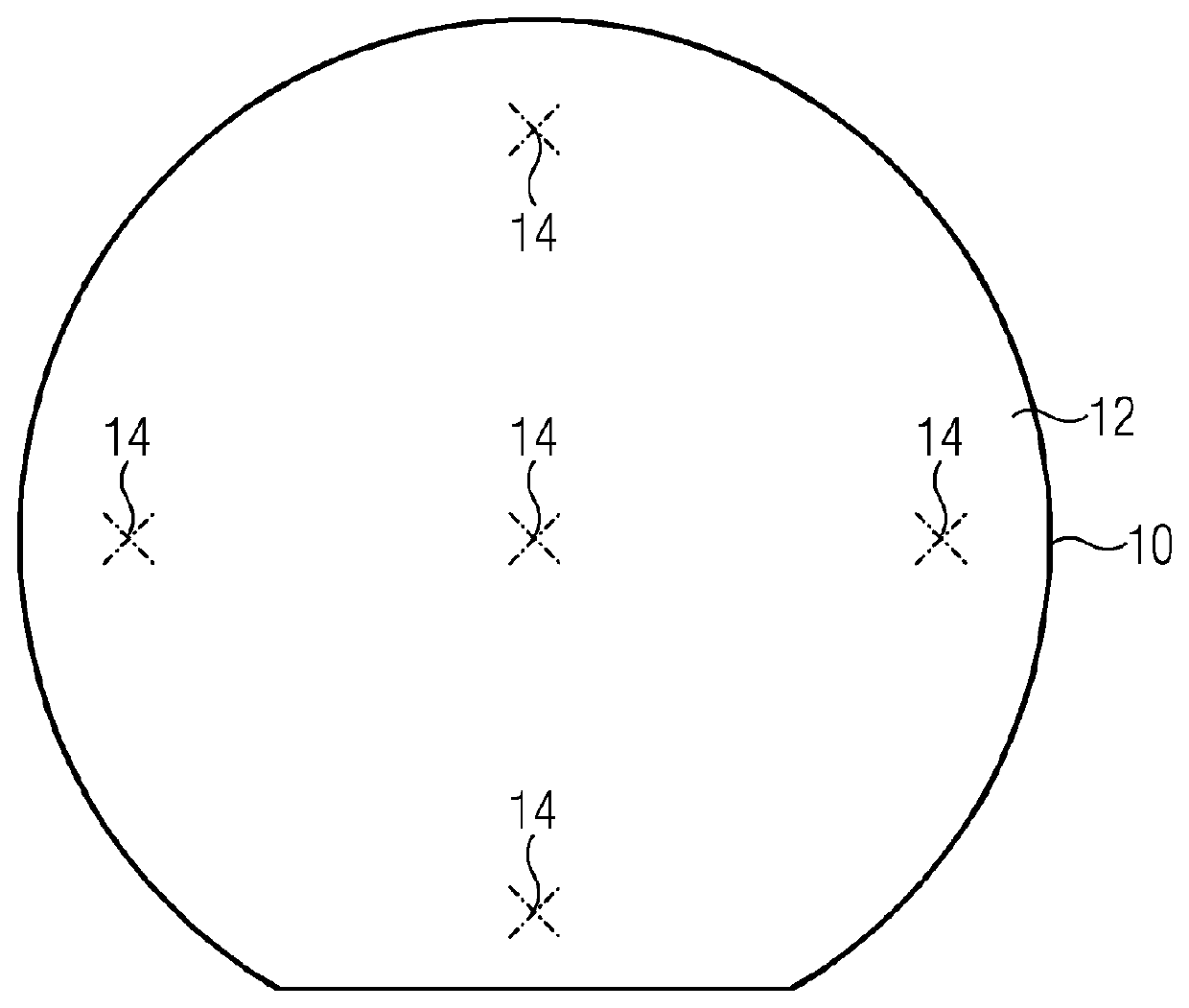
[0022]In order to produce a thin-film bulk acoustic resonator (FBAR), a layer of a piezoelectric ceramic (e.g., ZnO) enclosed between planar electrodes is produced on a substrate 10 (e.g., a silicon wafer). The layer is applied by deposition processes that are known (e.g., sputtering).

[0023]In order to achieve the desired resonator properties, and to make the excitation of shear modes possible, the polar axis of the piezoelectric material is to make an angle with the normal to the substrate surface. For this, a seed layer of about 100 nm thickness is produced. During deposition of this seed layer, a diaphragm system is installed between a source for the particles to be deposited and the substrate surface 12, providing shadowing of certain angles of incidence, so that the particles are deposited on the substrate surface 12 in a preferred orientation with the polar axis tilted in the desired way.

[0024]As soon as the desired seed layer thickness is reached, the diaphragm system may be ...


PUM

PropertyMeasurementUnit
thicknessaaaaaaaaaa
thicknessaaaaaaaaaa
angle of incidenceaaaaaaaaaa

Abstract

The invention relates to a method for producing a polycrystalline ceramic film on a surface (12) of a substrate (10), in which a particle stream is directed onto the surface (12) and the ceramic film is formed by deposition of the particles onto the surface (12), wherein the particle stream is directed by means of a diaphragm onto the surface (12) along a preferred direction until a first specified layer thickness is reached, the preferred direction and a surface normal of the surface (12) enclosing a specified angle of incidence. According to the invention, the diaphragm is removed from the particle stream after the specified layer thickness has been reached, and additional particles are directed onto the surface (12) until a specified second layer thickness has been reached.

Description

[0001]This application is the National Stage of International Application No. PCT / EP2013 / 062606, filed Jun. 18, 2013, which claims the benefit of DE 10 2012 211 314.2, filed Jun. 29, 2012. The entire contents of these documents are hereby incorporated herein by reference.BACKGROUND[0002]The present embodiments relate to producing a polycrystalline ceramic film.[0003]Thin-film bulk acoustic resonators (FBAR), which experience changes in resonant frequency on specific binding of substances to be detected on a surface, are increasingly finding application in the area of biosensors. These are piezoelectric crystal layers that are applied to appropriate substrates (e.g., Si wafers).[0004]Because the detection of biomolecules takes place in fluids, high resonance quality and sensitivity are to be provided. For this, the resonator is to be excited in the acoustic shear mode.[0005]In order to make such excitation possible, the polar crystal axis is to be inclined to the exciting field. In a...

Claims


Application Information

Patent Timeline
Patent Type & Authority Patents(United States)
IPC IPC(8): C23C14/34C23C14/08H01L41/316C23C14/54H03H9/17C23C14/06C23C14/00H01J37/34
CPCC23C14/542C23C14/086C23C14/0036H03H9/171H01L41/316C23C14/548H01J37/3447C23C14/0641C23C14/0068C23C14/044C23C14/0617C23C14/225H03H3/02H10N30/076
Inventor SCHREITER, MATTHIASWERSING, WOLFRAM
Owner BIOMENSIO LTD
Why Eureka
Try Eureka