Signal processing methods

a technology of signal processing and signal, applied in the field of signal processing methods, can solve the problems of high ill-posed inverse problem and inability to solve the above equations

Active Publication Date: 2020-02-11
CAMBRIDGE ENTERPRISE LTD
View PDF16 Cites 0 Cited by
  • Summary
  • Abstract
  • Description
  • Claims
  • Application Information

AI Technical Summary

Benefits of technology

[0028]In some preferred implementations of the technique the inverse problem is solved for EEG by determining the scalar value ψ representing an irrotational part of the 3D current distribution by writing ψ in terms of a set of basis functions having respective unknown coefficients λi defined by a vector λ. In some preferred embodiments radial basis functions are employed, which is convenient, but the skilled person will appreciate that other basis functions may also be employed. Such an expansion enables the integral equation to be reformulated as a set of equations represented by a matrix equation:b=E·λwhere b comprises a vector of the electric potential measurements on the scalp. This is straightforward to solve to determine an estimate of λ using a least squares approach. In the above matrix equation the matrix E has the substantial advantage that elements of the matrix depend only on the geometry and conductivity of the model of the head (and the basic functions). Thus although relatively computationally expensive to calculate, the elements of matrix E may be pre-computed and stored for use in solving the EEG inverse problem. Broadly speaking, determining an estimate for λ then reduces to a matrix inversion. The skilled person will appreciate that there are many different techniques which may be employed to solve the above matrix equation.

Problems solved by technology

However these methods rely on local optimisation and suffer from getting trapped by local minima.
However there exists an infinite number of distributions of current sources which can generate the same scalp electric potential and the same magnetic field outside the head and thus the inverse problem is highly ill-posed.
This in turn necessitates the use of various assumptions which are often inappropriate; the technique also suffers from ‘cross-talk’ in that the activity at an arbitrary location is contaminated by activity from other brain regions.
However there is a problem in that the above equations cannot readily be solved.

Method used


Image

  • Signal processing methods
  • Signal processing methods
  • Signal processing methods

Examples


Embodiment Construction

1. Framework

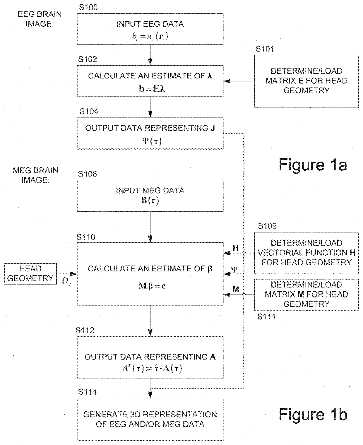
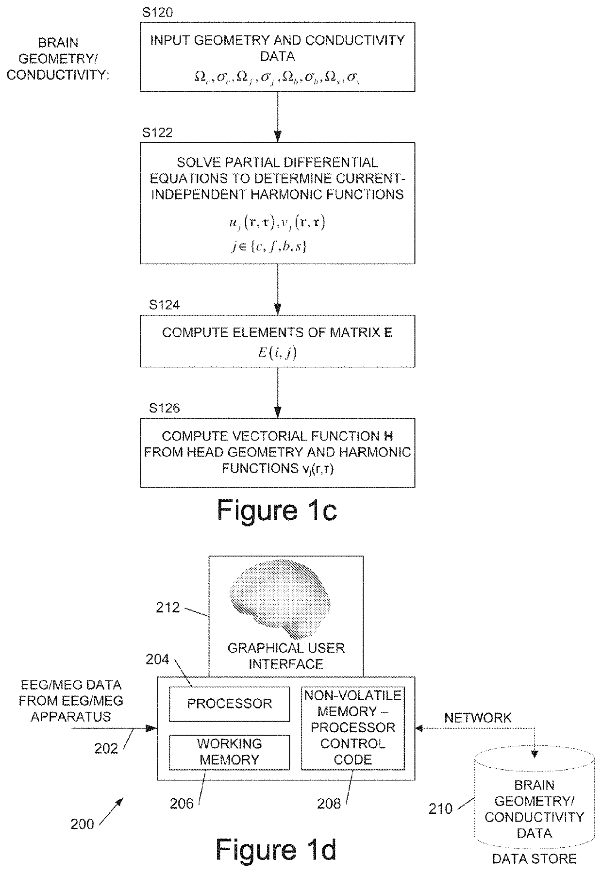
[0057]In the following description we denote a domain and its conductivity by Ω⊂R3 and σ respectively. Let the bounded domain Ωc represent the cerebrum, which has conductivity σc. A shell Ωƒ with conductivity σƒ, representing the cerebrospinal fluid (CSF), surrounds the domain Ωc. The CSF is surrounded by the skull characterized by the domain Ωb with conductivity σb. Finally, the skull is surrounded by the scalp, which is modelled as a shell Ωs with conductivity σs. The domain exterior to the head is denoted by Ωe which is not conductive. The permeability of all domains is equal to the permeability μ0 of empty space. Let JP(τ), τ∈Ωc, denote the current which is supported within the cerebrum Ωc. For the above situation of arbitrary geometry and arbitrary current, it is shown in A S Fokas (J. R. Soc. Interface, 6:479-488, 2009, ibid) that the irrotational part of the current, which is denoted by the scalar function Ψ(τ), contributes to both the electric potential on the sc...


PUM


Abstract

We describe a method of processing an EEG and / or MEG signal to generate image data representing a 3D current distribution, J, within the brain, the method comprising: capturing a plurality of electric and / or magnetic measurements from the exterior of the head; solving an integral equation for a part of said current distribution to generate said image data representing said 3D current distribution, wherein said integral equation comprises an integral of a first function representing said part of said current distribution and of a second function (∇Tvs(r,τ)) representing the geometry and conductivity of the head independent of said current distribution; wherein said solving comprises: modelling the head as at least two regions separated by at least one internal boundary, and solving a set of partial differential equations, one for each said internal region, each partial differential equation comprising a geometry-conductivity function (w(r,τ)) representing the geometry and conductivity of the respective region, wherein said solving is subject to a boundary condition that either i) the gradients of the functions across the or each said internal boundary are smooth when conductivity is taken into account, or ii) a normal component of the electric field of said part of said current distribution is continuous across the or each said internal boundary, and wherein said geometry-conductivity function for an outermost said region of said head defines said second function (∇Tvs(r,τ)).

Description

RELATED APPLICATIONS[0001]This application is a 371 U.S. National Stage Application of International Application No. PCT / GB2015 / 051597, entitled “SIGNAL PROCESSING METHODS,” filed Jun. 1, 2015, which claims priority to Great Britain application no. 1409766.1, filed on Jun. 2, 2014, both of which are hereby incorporated by reference in their entirety for all purposes.FIELD OF THE INVENTION[0002]This invention relates to methods, apparatus, and computer program code for generating image data from EEG (electroencephalography) and / or MEG (magnetoencephalography) signals.BACKGROUND TO THE INVENTION[0003]Active neurons produce small currents whose basis is the change in the concentration of certain ions (ionic currents). The flow of current in the neural system produces a weak magnetic field. The measurement of this field outside the head and the estimation of the neuronal current which produced this field is called Magnetoencephalography (MEG). In spite of the fact that neuromagnetic sig...

Claims


Application Information

Patent Timeline
Patent Type & Authority Patents(United States)
IPC IPC(8): A61B5/04G06T7/60G06T7/73A61B5/0476G06T7/00A61B5/00G06T7/13G06T7/11
CPCG06T7/73G06T7/0012G06T7/60A61B5/0476G06T7/13A61B5/7239A61B5/04012A61B5/04005G06T7/11A61B5/7242G06T2207/30016A61B5/369G06F2218/22A61B5/316A61B5/242
Inventor FOKAS, ATHANASSIOS SPYRIDONHASHEMZADEH, PARHAM
Owner CAMBRIDGE ENTERPRISE LTD
Why Eureka
Try Eureka