Method and a system for estimating a stream temperature in a turbojet

a technology of estimating parameters and turbojets, which is applied in the direction of temperature measurement of flowing materials, instruments, heat measurement, etc., can solve the problems of high cost of sensors, general temperature sensors, and malfunctions of jet engines, and achieve accurate and dynamic requirements and low cost.

Active Publication Date: 2011-10-06
SN DETUDE & DE CONSTR DE MOTEURS DAVIATION S N E C M A
View PDF7 Cites 1 Cited by
  • Summary
  • Abstract
  • Description
  • Claims
  • Application Information

AI Technical Summary

Benefits of technology

[0020]As a result, expensive calculations for estimating the time constant of the sensor are avoided, thereby lightening the load on the computer of the turbojet, i.e. typically on the full authority digital engine controller (FADEC).
[0034]Advantageously, this value may be used in particular for initializing the adaptive algorithm for updating the error signal, instead of using a predetermined initial value (e.g. zero). This can serve to accelerate the convergence of the adaptive algorithm or it may be used as a default value for the error signal while waiting to detect a stage of temperature stability after starting the turbojet.

Problems solved by technology

Temperature sensors generally suffer during a measurement from thermal inertia that is specific to each sensor and that depends in particular on the mass or the size of the sensor.
This is referred to as the measurement lag effect and can cause malfunctions of the jet engine because of measurement mismatch, in particular during rapid variations in the temperatures of the gas streams.
Nevertheless, such sensors are very expensive.
Current fabrication technologies do not enable temperature sensors for controlling jet engines to be produced at low cost and that also comply with a response time template subject to little spread.
Consequently, it is difficult to obtain graphs adapted to the various temperature sensors concerned.
Numerous problems have arisen when the time constants of the sensors mounted in a jet engine depart considerably from the values given by these graphs.
Such a test is particularly costly, however, and represents approximately one-third of the price of the temperature sensor.
Consequently, it cannot be used for each temperature sensor, which means that a temperature sensor outside an acceptance template for which a graph is available might not be detected.
Furthermore, such tests are often carried out at fluid flow rates limited by the capacities of a wind tunnel and they are generally not able to cover the range of working flow rates in jet engine applications.
Consequently, it is necessary to use additional estimator modules on the jet engine, which makes correcting measurements even more complex.

Method used


Image

  • Method and a system for estimating a stream temperature in a turbojet
  • Method and a system for estimating a stream temperature in a turbojet
  • Method and a system for estimating a stream temperature in a turbojet

Examples


Embodiment Construction

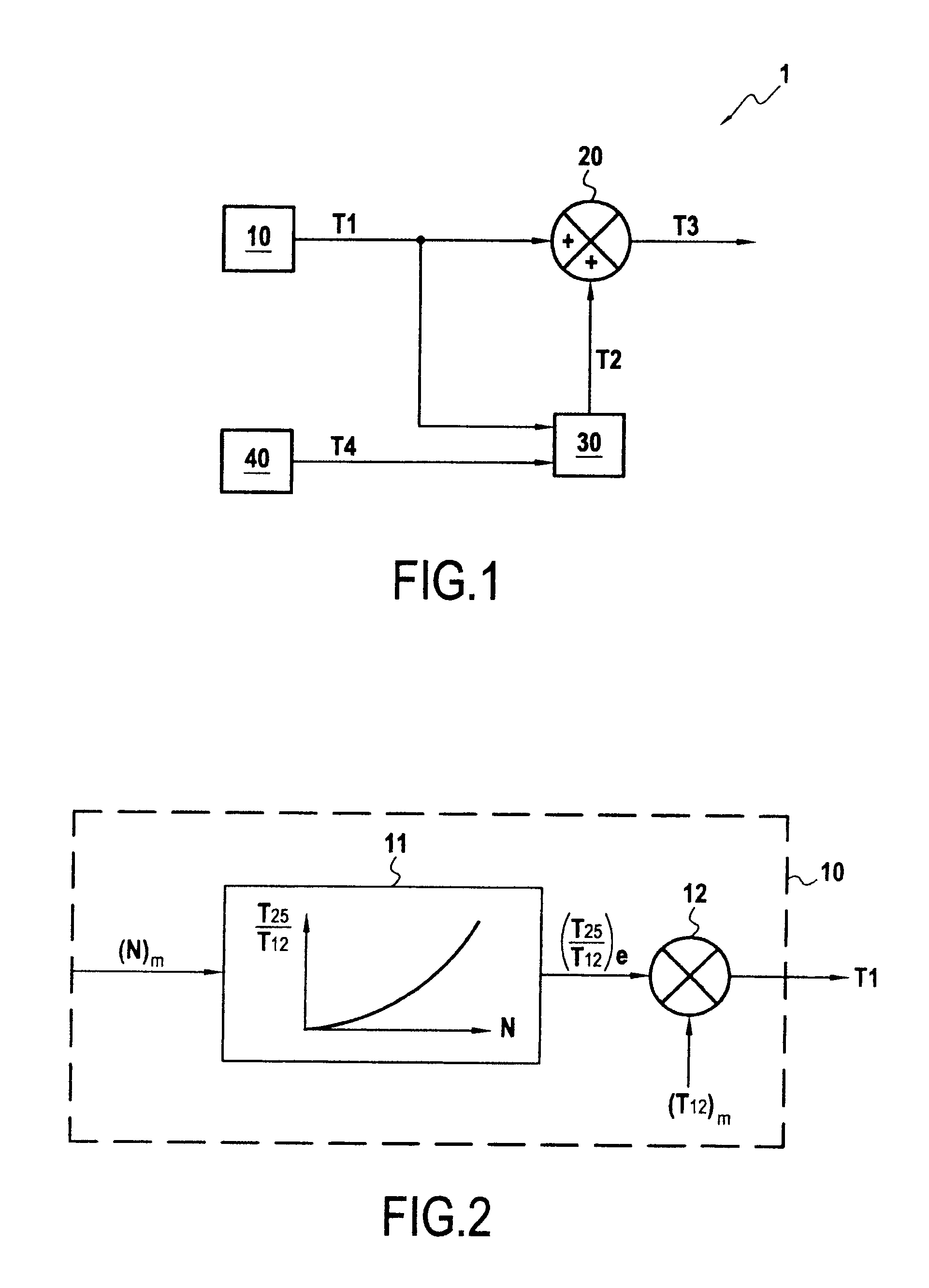
[0046]FIG. 1 shows a particular embodiment in accordance with the invention of an estimator system 1 for estimating a stream temperature in an airplane turbojet (not shown in the figure).

[0047]The estimated flow passage temperature may be used in particular for regulating and controlling the turbojet. Thus, in the embodiment described herein, all or part of the estimator system 1 is coupled to or incorporated in the full authority digital engine controller (FADEC) device of the airplane propelled by the turbojet.

[0048]Nevertheless, and naturally, other uses may be envisaged for the stream temperature estimated by using the method of the invention.

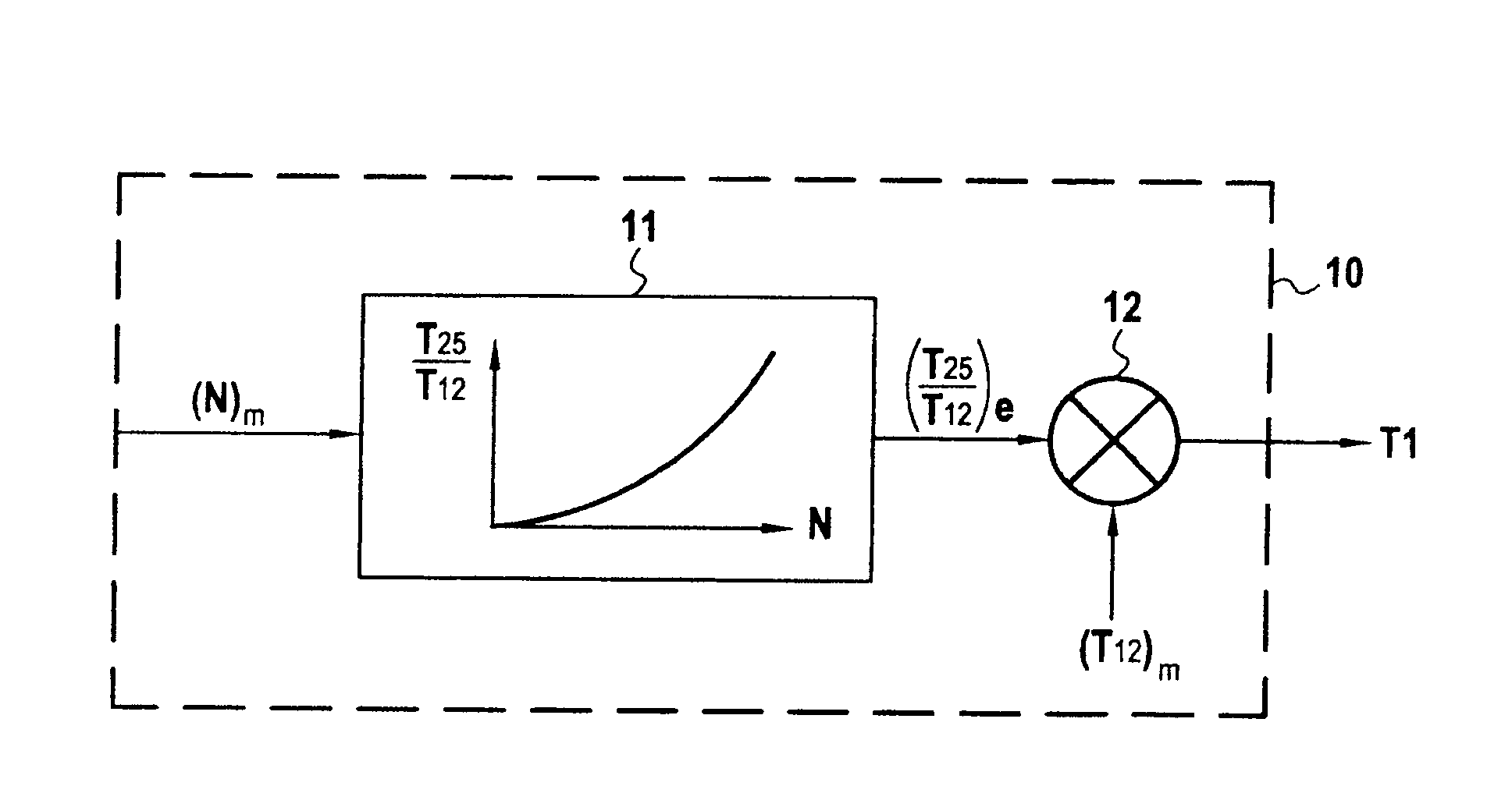
[0049]In the example described, it is the stream temperature T25 at the inlet of the high pressure compressors of the turbojet that is to be estimated.

[0050]In accordance with the invention, the estimator system 1 comprises a digital modeling module 10 used for modeling the stream temperature T25.

[0051]The signal T1 delivered by the digital...


PUM


Abstract

An estimation method that can estimate a stream temperature in a turbojet including: digitally modeling the stream temperature with help of a modeled signal; and correcting the modeled signal with help of an error signal, a signal obtained after correction representing an estimate of the stream temperature. When predetermined conditions relating to at least one operating stage of a turbojet and to temperature stability are satisfied, the error signal is updated from the modeled signal and from a measurement signal of the stream temperature as delivered by a temperature sensor.

Description

BACKGROUND OF THE INVENTION[0001]The invention relates to the general field of aviation.[0002]More particularly, it relates to estimating parameters in an aircraft turbojet, such as the temperature of a fluid, for example.[0003]A preferred but non-limiting application of the invention lies in the field of systems for regulating and controlling turbojets.[0004]In known manner, in order to regulate and adapt the control of a turbojet to various flight constraints, it is necessary to estimate the temperature of various gas streams passing through the turbojet (referred to as stream temperatures). For this purpose, use is made of temperature sensors such as probes or thermocouples that are positioned in various locations in the gas streams and that are adapted to measure the temperatures of said gas streams.[0005]Temperature sensors generally suffer during a measurement from thermal inertia that is specific to each sensor and that depends in particular on the mass or the size of the sen...

Claims


Application Information

Patent Timeline
Patent Type & Authority Applications(United States)
IPC IPC(8): G06F17/10
CPCG01K7/42G01K2013/024G01K13/02G01K13/024
Inventor DJELASSI, CEDRIKGAULLY, BRUNO ROBERT
Owner SN DETUDE & DE CONSTR DE MOTEURS DAVIATION S N E C M A
Why Eureka
Try Eureka