
Writing tool

a writing tool and writing technology, applied in the field of writing tools, can solve the problems of restricting the simultaneous plentiful gas-liquid exchange, and achieve the effects of enhancing the dispensing efficiency of ink, destroying the surface tension of ink, and avoiding lateral ink leakage and abnormal ink dispensing

Active Publication Date: 2020-02-25
SDI CORPORATION
View PDF28 Cites 1 Cited by
  • Summary
  • Abstract
  • Description
  • Claims
  • Application Information

AI Technical Summary

Benefits of technology

The present invention aims to solve the problem of ink leakage and redundant ink dispensed to the cotton core of the conventional writing tool during ink dispensing. The invention provides a writing tool with a pressing segment and a dispensing interval on a communicating tube of a dispensing unit. The dispensing unit applies different pressures to a capillary unit via the pressing segment and the dispensing interval in order to prevent ink from tending to be detained. The dispensing interval formed between the pressing segment and the communicating tube can effectively destroy surface tension of ink, thereby enhancing the dispensing efficiency of the ink. The internal periphery of the communicating tube also stops lateral overflow of the ink, thereby avoiding the lateral ink leakage and abnormal ink dispensing. The pressing segment and the communicating tube can apply different compression densities to the capillary unit, thereby detaining the ink within different parts of the capillary unit. The invention solves the problem of ink leakage and ensures smooth ink dispensing.

Problems solved by technology

After the ink is diffused to be dispensed, the air substitutes it, further restricting the simultaneous plentiful gas-liquid exchange.

Method used


Image

  • Writing tool
  • Writing tool
  • Writing tool

Examples


Embodiment Construction

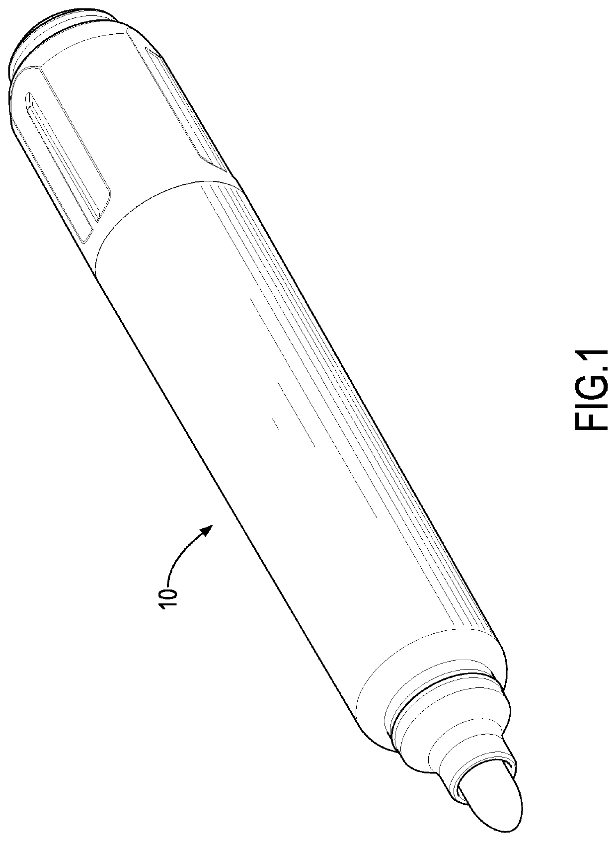
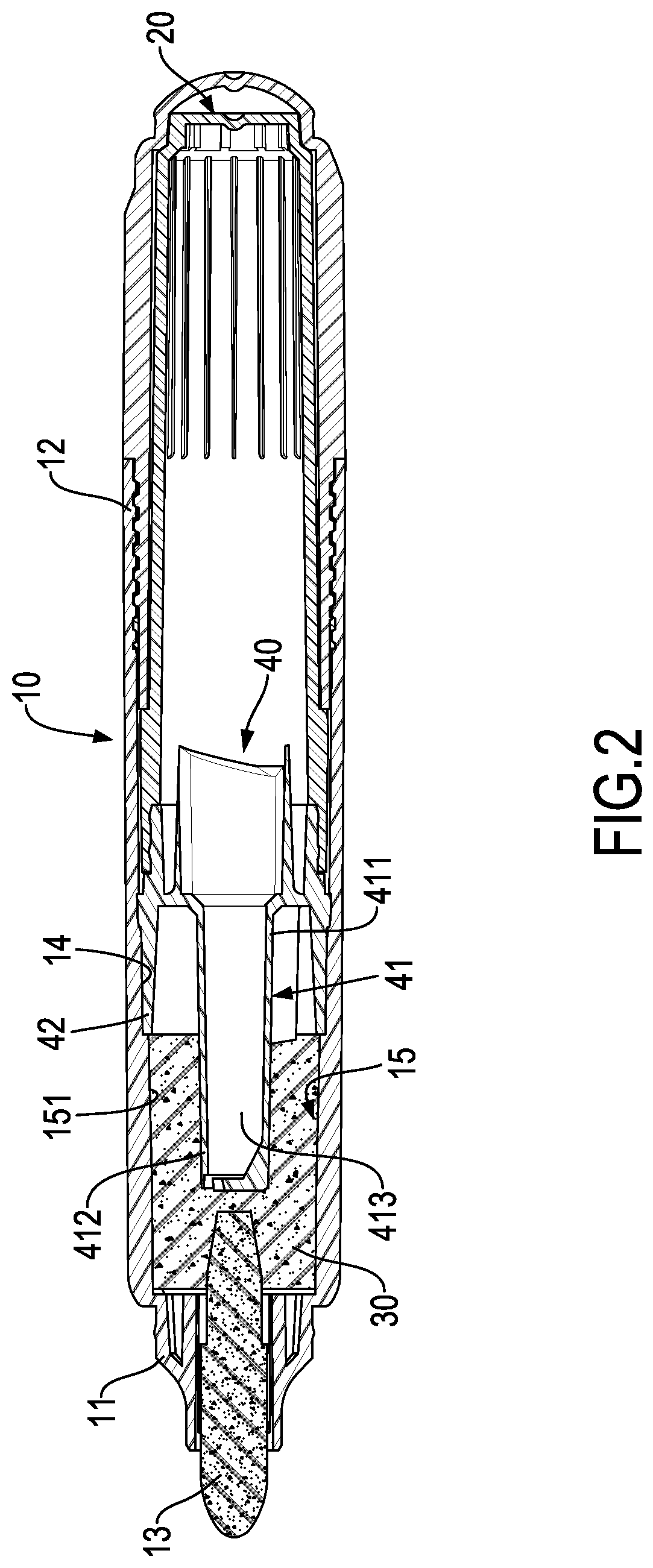
With reference to FIGS. 1, 2, 6, and 7, a writing tool constructed in accordance with a first preferred embodiment of the present invention includes a pen tube 10, an ink cartridge 20, a capillary unit 30, and a dispensing unit 40.

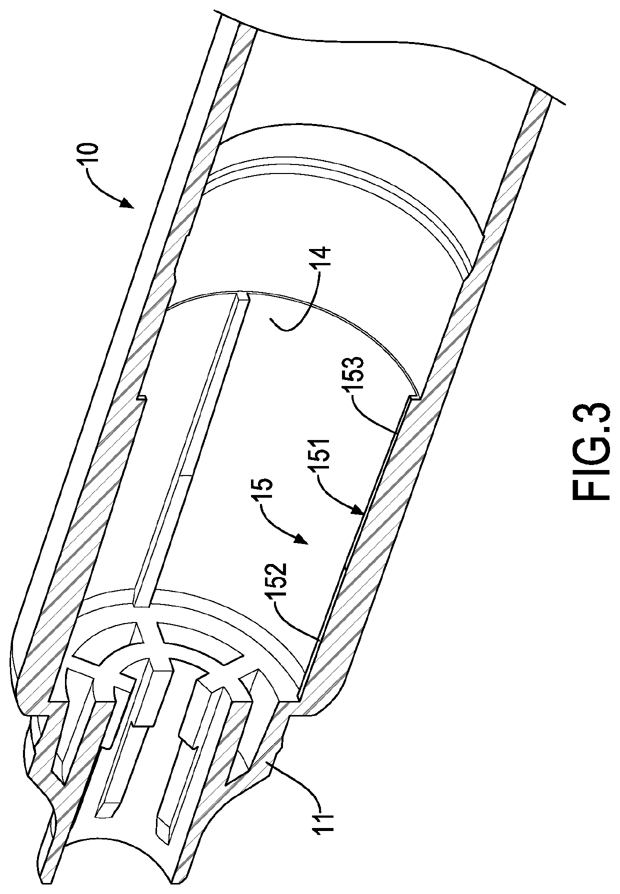
The pen tube 10 has a first end 11, a second end 12, and a nib 13. The pen tube 10 is a tube extending lengthwise. The first end 11 and the second end 12 are defined as two opposite ends of the pen tube 10, respectively. The nib 13 is mounted to the first end 11 of the pen tube 10. The pen tube 10 includes an internal periphery 14 between the first end 11 and the second end 12. In a preferred embodiment, the pen tube 10 further includes a pressing portion 15 formed on the internal periphery 14 and located adjacent to the first end 11. The pressing portion 15 includes a plurality of protrusive ribs 151 protruding inwardly from the internal periphery 14 of the pen tube 10.

With reference to FIG. 2, the ink cartridge 20 is detachably mounted to the second end ...


PUM


Abstract

A writing tool has a pen tube, a capillary unit, and a dispensing unit. The capillary unit is mounted in the pen tube, and is connected to a nib. The dispensing unit is mounted in the pen tube, and has a communicating tube and a pressing segment connected to the communicating tube. The pressing segment has at least one connecting arm connected to the communicating tube. A dispensing interval is formed between the communicating tube and a periphery of the pressing segment. The communicating tube contacts the capillary unit to make the capillary unit form different compression densities via the pressing segment and the dispensing interval, thus facilitating dispensing ink downward easily through the dispensing interval and providing a better occlusion effect to further avoid ink leakage.

Description

CROSS-REFERENCE TO RELATED APPLICATIONSThis application is based upon and claims priority under 35 U.S.C. 119 from Taiwan Patent Application No. 106131962 filed on Sep. 18, 2017, which is hereby specifically incorporated herein by this reference thereto.BACKGROUND OF THE INVENTION1. Field of the InventionThe present invention relates to a writing tool, and particularly to a writing tool that can smoothly dispense ink and avoid ink leakage.2. Description of the Prior ArtsA conventional writing tool as shown in China Patent Publication No. CN102844199A discloses an applicator having a channel 5 in which an application liquid 7 is flowable. The channel 5 includes a protrusion 11, the protrusion 11 having a cavity 21 therein and at least two communication holes 13, 14 partially communicating with the cavity 21, thereby allowing the application liquid 7 and external air to be dispensed outwardly and introduced inwardly via the communication holes 13, 14, respectively.However, in the firs...

Claims


Application Information

Patent Timeline
Patent Type & Authority Patents(United States)
IPC IPC(8): B43K1/00B43K8/00B43K8/12B43K5/18B43K8/14B43K8/03B43K8/02B43K5/14
CPCB43K1/003B43K5/14B43K5/18B43K8/146B43K8/03B43K8/12B43K8/022B43K5/1818B43K1/01B43K5/02B43K5/005B43K5/00
Inventor CHEN, SZU-YU
Owner SDI CORPORATION
Learn More