Container orifice reducer with tamper evident seal

a technology of orifice reducer and seal, which is applied in the field of containers, can solve the problems of affecting so as to achieve the effect of enhancing the shelf life of the produ

Active Publication Date: 2020-02-25
CSP TECH INC
View PDF38 Cites 5 Cited by
  • Summary
  • Abstract
  • Description
  • Claims
  • Application Information

AI Technical Summary

Benefits of technology

Optionally, an injection molded polymer orifice reducer according to the invention may vary in thickness and may be constructed in one or more pieces to accommodate a metered orifice. For example, such configuration may enable a user to manually push or rotate a portion of the orifice reducer to increase or decrease the dispensing opening to provide a desired metered dispense rate. Optionally (e.g. for liquids or powders), the dispensing opening may include an option for fixing a spout thereto, such as a movable cylindrical spout, which can be raised upward for pouring contents, after the tamper evident seal has been removed. Optionally, the injection molded orifice reducer may be recessed below the container opening to allow physical separation from the flexible seal. For any embodiment, the top surface of the orifice reducer may include a small flip top hinge to allow the user to re-seal the orifice after removing the foil. Such a re-closable orifice reducer may enhance the shelf-life of the product in the container. Optionally, more than one of the foregoing optional embodiments may be combined. For example, a flip top re-sealable lid may be permanently attached to the injection molded polymer orifice reducer dispensing opening, which can be resealed after the tamper evident flexible seal has been removed. Such re-sealable lid does not touch the tamper evident flexible seal during induction sealing or in-mold labeling, if the orifice reducer is recessed below the container opening.

Problems solved by technology

When the target material (e.g., foil seal) is exposed to the electromagnetic field, eddy currents are created in the target material, causing the target material to heat up because of resistance losses.
One disadvantage of standard bottles is that once the tamper-proof seal is removed, the opening is typically very large (e.g., an inch, give or take) such that tilting the bottle to remove a single tablet / capsule often results in several tablets / capsules falling out at once.
A similar problem can occur with such bottles having liquid or powder contents, where too much of the liquid or powder may pour out at once.
Alternatively, a user may reach a finger into the bottle to retrieve a single tablet / capsule, thereby contaminating the contents of the bottle.
While various dispensing means have been previously proposed, they often involve complicated and expensive to manufacture moving parts (e.g., springs, actuators and the like) and / or present manufacturing challenges, particularly when it is desired to apply both a tamper-proof seal and dispensing means to a filled bottle.
For example, one challenge in achieving the desired objective relates to the manner in which the bottles are made and filled.
Where a container is to be prefilled, it is generally not practical or possible to have the orifice reducer in place prior to filling, since the orifice reducer obstructs some or much of the container opening.

Method used


Image

  • Container orifice reducer with tamper evident seal
  • Container orifice reducer with tamper evident seal
  • Container orifice reducer with tamper evident seal

Examples


Embodiment Construction

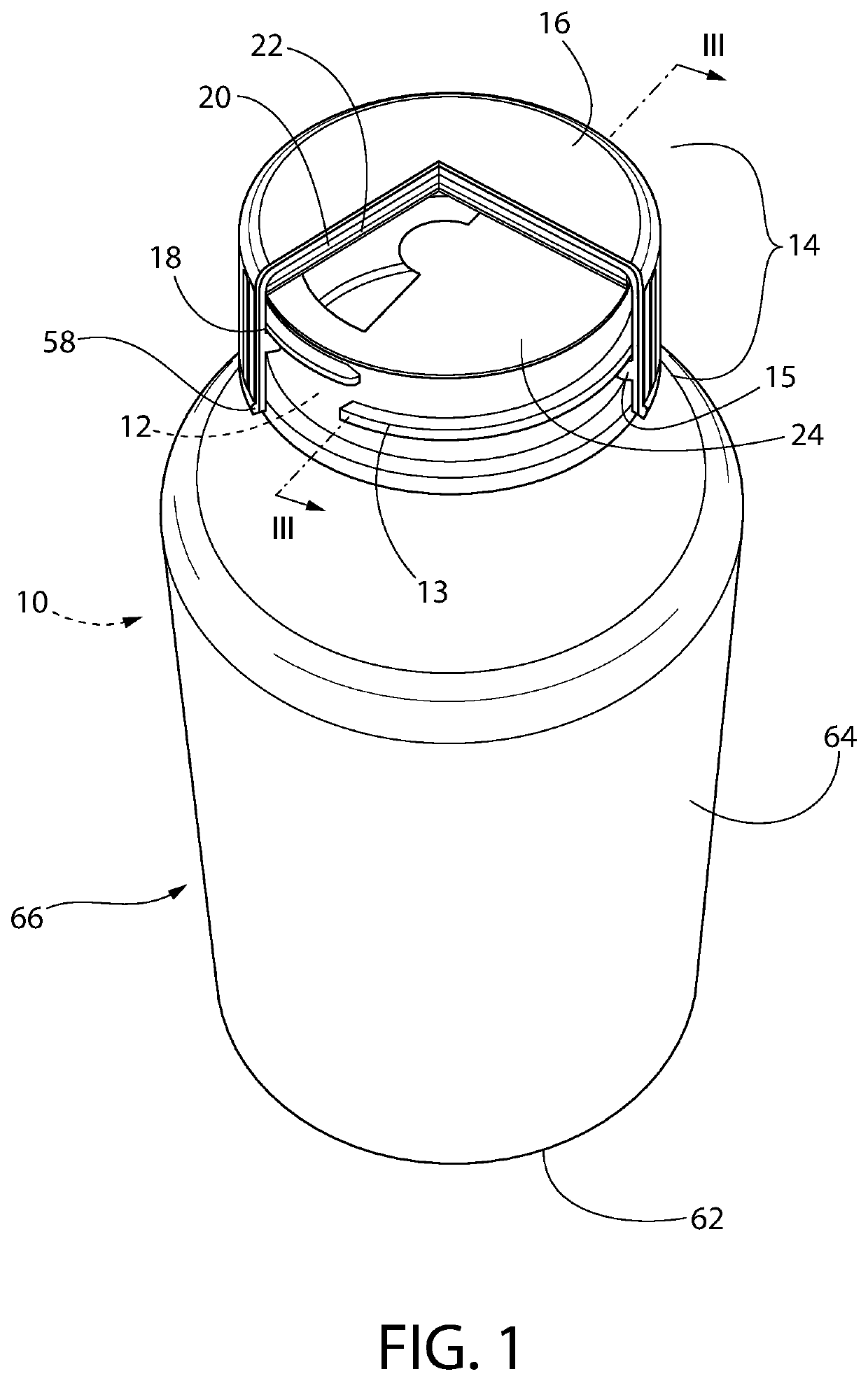
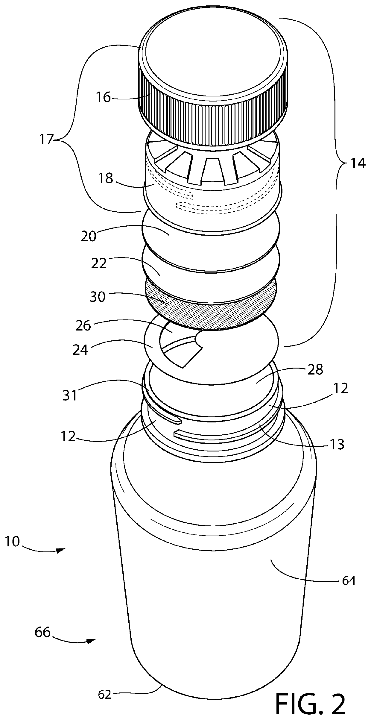
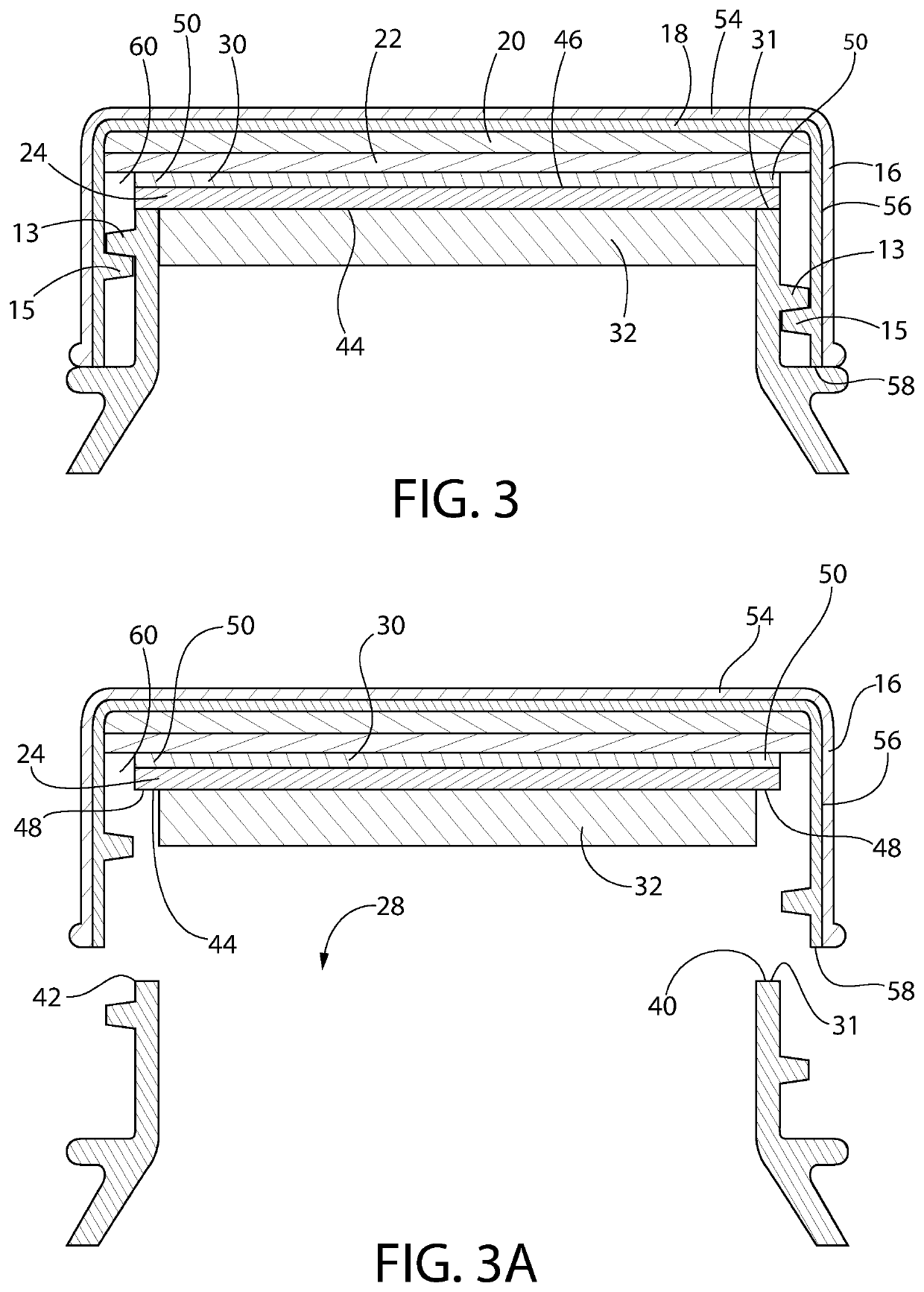
Referring now in detail to the various figures of the drawings wherein like reference numerals refer to like parts, there is shown in FIGS. 1-3 various views of a container 10 in the form of a bottle, having an exemplary orifice reducer 24 permanently secured thereto. While the bottle is one contemplated type of container that may be used in conjunction with the present invention, other types of containers are also contemplated. It should be understood that where the term “bottle” is used to describe an exemplary embodiment, the broader, more generic term “container” may also be used in its place.

A container 10 according to an exemplary embodiment includes a body 66 having a base 62 and one or more sidewalls 64 extending from the base 62, leading to a rim 31 surrounding an opening 28 of the container. The embodiment shown is cylindrical and thus has a round, unitary sidewall 64. However, containers according to the invention may be other shapes, e.g., rectangular cuboid, and thus ha...


PUM

PropertyMeasurementUnit
thicknessaaaaaaaaaa
thicknessaaaaaaaaaa
thicknessaaaaaaaaaa

Abstract

Containers with closures are disclosed. A closure may include at least a polymer orifice reducer configured to be permanently secured to a rim of an opening of a container and a flexible tamper evident seal disposed on the topside of the orifice reducer. The flexible tamper evident seal, optionally foil, covers one or more openings in the orifice reducer. Processes for permanently securing a closure to a container, optionally by forming a heat seal between the orifice reducer and container rim, are also disclosed.

Description

BACKGROUND OF THE INVENTION1. Field of InventionThis invention relates to containers having a flexible seal (e.g., foil) for product-preservation and tamper evidence as well as an orifice reducer for product dispensing. The invention may be used for many different applications and industries, including, e.g., pharmaceuticals and nutraceuticals (e.g., tablets, capsules and liquids), foods (e.g., spice bottles) and chemical dispensing (e.g., pool or cleaning chemicals). Product forms contemplated include, among others, liquids, tablets, capsules, pellets, powders, granules and other small solid units.2. Description of Related ArtCommercial medicine containers, e.g., for tablets and capsules, are typically provided as plastic bottles with removable caps (often having some type of child-resistance configuration). For example, over the counter (OTC) pain relief tablets, allergy medications, as well as nutraceuticals and vitamins, are often provided in such bottles. Typically, to ensure a...

Claims


Application Information

Patent Timeline
Patent Type & Authority Patents(United States)
IPC IPC(8): B65D77/20B65D41/34A61J1/03B65D1/02
CPCB65D41/3495B65D1/0223A61J1/03A61J1/1418B65D47/043B65D50/041B65D51/20B65D51/244B65D83/04B65D83/06B65D2215/02B65D2251/0015B65D2251/0093B65D2401/15
Inventor GIRAUD, JEAN-PIERRELUCAS, JR., FRANKLIN LEE
Owner CSP TECH INC
Why Eureka
Try Eureka