Flow measurement arrangement including a flow tube and an elastically deformable orifice plate with strain sensors

a technology of strain sensors and flow tubes, applied in the direction of volume/mass flow measurement, measurement devices, instruments, etc., can solve the problems of difficult to accommodate strain sensors in the through-flow measurement arrangement, and achieve the effect of high reproducibility, easy adaptation to different measuring tasks

Active Publication Date: 2020-02-25
SIEMENS AG
View PDF15 Cites 1 Cited by
  • Summary
  • Abstract
  • Description
  • Claims
  • Application Information

AI Technical Summary

Benefits of technology

It is an object of the invention to provide a through-flow measurement arrangement having a simple structural design and that is simultaneously suitable for use in a measuring transmitter for process instrumentation.
The one-piece embodiment of the measuring diaphragm and tube enables the through-flow measurement arrangement in accordance with the invention to be produced reproducibly in a much simpler way and with higher precision than is possible with the conventional through-flow measurement arrangement disclosed in DE 1 943 021 A. The fillet groove in the region connecting the tube and measuring diaphragm creates a bending joint directly where the measuring diaphragm meets the tube in a rectangular shape or T-shape. At this point, the material deformation is greatest on the deflection of the measuring diaphragm so that the strain sensor arranged on the circumferential side of the tube opposite the fillet groove supplies a maximum signal. The local single bending on the bending joint is greater than would be the case with spatially extending multiple bending of the tube wall if the deformation of the measuring diaphragm were transmitted to the tube wall in a positive and non-positive manner. Finally, with the through-flow measurement arrangement in accordance with the invention, the strain sensor is arranged on the circumferential side of the tube in a manner that is easily accessible and simple to install and contact.
Preferably, the at least one strain sensor is arranged in a recess on the circumferential side of the tube. With round tubes, on the one hand, the recess offers a flat installation surface for the strain sensor and, on the other, due to the reduced thickness of the tube wall, enables optimum dimensioning of the bending joint without this necessitating the fillet groove to be formed too deep and hence also too wide.
In order to avoid unnecessary material stresses in the region between the bending joints and for a more flexible design of the bending joints on the deflection of the measuring diaphragm, a slit extending centrally between them toward the measuring diaphragm can be provided, which extends into the measuring diaphragm from the circumferential side of the tube to a part. This causes the bending joint to be extended into the slit so that at least one further strain sensor can be arranged therein opposite the fillet groove. The further strain sensor is arranged at the start of the slit close to the circumferential side of the tube. As a result, it is not difficult to install in the slit.
The through-flow measurement arrangement in accordance with the invention can be easily adapted to different measuring tasks in that a restrictor is inserted into the opening of the measuring diaphragm as a replaceable part. The restrictor can be, for example, a diaphragm insert, a nozzle or a Venturi tube.
The through-flow measurement arrangement in accordance with the invention, which can be produced with high and reproducible precision, is accordingly robust. As a result, it is particularly suitable for use as a measuring cell or sensor in a measuring transducer for process instrumentation.

Problems solved by technology

Therefore, it is difficult to accommodate the strain sensors in the through-flow measurement arrangement only toward the end of the through-flow measurement arrangement assembly.
On the other hand, if the strain sensors are attached to the diaphragms in advance, they could be damaged when the diaphragms are later connected to the other parts of the through-flow measurement arrangement, such as welded thereto.
A pressure difference applied to the partition diaphragm results in the deformation thereof.

Method used


Image

  • Flow measurement arrangement including a flow tube and an elastically deformable orifice plate with strain sensors
  • Flow measurement arrangement including a flow tube and an elastically deformable orifice plate with strain sensors
  • Flow measurement arrangement including a flow tube and an elastically deformable orifice plate with strain sensors

Examples


Embodiment Construction

In the figures, the same parts are given the same reference numbers.

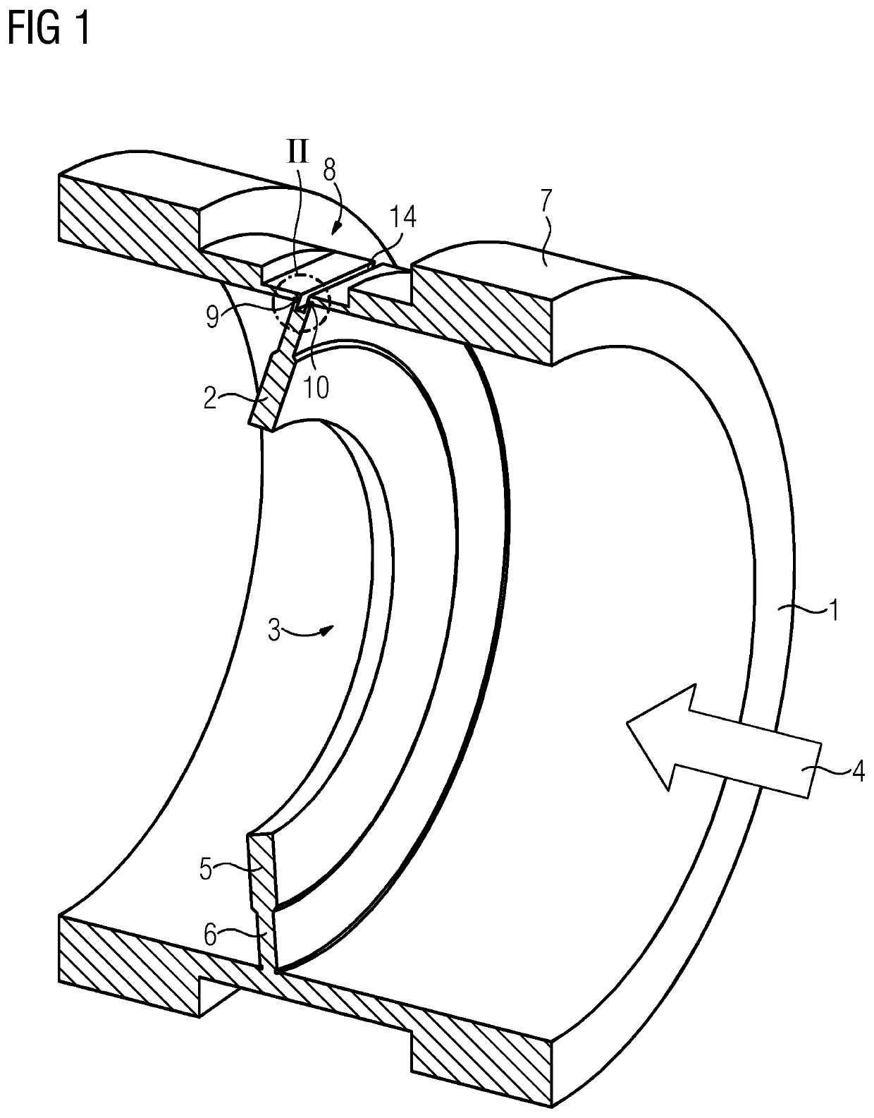
FIG. 1 shows a longitudinal section through a tube 1 in which an elastically deformable measuring diaphragm 2 (or orifice plate) is arranged in its cross section. The measuring diaphragm 2 and the tube 1 are formed in one piece from a uniform material, such as steel. In its center, the measuring diaphragm 2 comprises a diaphragm opening 3 via which the cross section of the tube is constricted for a flowing medium 4. Therefore, the flowing medium 4 causes a pressure drop over the measuring diaphragm 2 so that it becomes deformed and deflected. In the example shown, in its central region 5 around its opening 3, the measuring diaphragm 2 has a greater thickness than in its outer region 6, by which it is connected to the tube 1. The tube 1 contains on its circumferential side 7, in a region opposite the measuring diaphragm 2, a recess 8. As a result, the wall thickness of the tube 1 is reduced on both sides of the measu...


PUM


Abstract

A flow measurement arrangement and measuring transmitter for process instrumentation that includes the flow measurement arrangement, wherein the flow measurement arrangement operating in accordance with the differential-pressure method includes a tube and an elastically deformable measuring diaphragm (orifice plate) arranged in the cross section of the tube and a strain sensor that detects the deformation and converts it into an electric signal, where the measuring diaphragm (orifice plate) and the tube are formed in one piece from uniform material, and where both side of the measuring diaphragm (orifice plate) each pass into the tube via a fillet groove and the at least one strain sensor is arranged on the circumferential side of the tube opposite the fillet groove.

Description

BACKGROUND OF THE INVENTION1. Field of the InventionThe invention relates to a through-flow measurement arrangement operating in accordance with the differential-pressure method and including a tube and an elastically deformable measuring diaphragm (orifice plate) is arranged in the cross section of the tube and a strain sensor that detects the deformation of the diaphragm (orifice plate) and converts the deformation into an electric signal, and also relates to a measuring transmitter for process instrumentation having such a through-flow measurement arrangement.2. Description of the Related ArtDE 1 943 021 A discloses a conventional through-flow measurement arrangement.In the case of through-flow measurement in accordance with the differential pressure method, the cross section of tubing is constricted at one point by the insertion of a restrictor (e.g. diaphragm, nozzle, Venturi tube). The constriction causes the rate of flow to increase with the same volume through-flow. The pres...

Claims


Application Information

Patent Timeline
Patent Type & Authority Patents(United States)
IPC IPC(8): G01F1/38G01F1/42
CPCG01F1/38G01F1/383G01F1/42
Inventor ERDLER, GILBERT ALEXANDERVON DOSKY, STEFANENS, WOLFGANG
Owner SIEMENS AG
Why Eureka
Try Eureka