
Greenhouse for plant cultivation

a technology for plant cultivation and greenhouses, applied in greenhouse cultivation, saving energy measures, agriculture tools and machines, etc., can solve the problems of degrading the thermal insulation effect of the greenhouse and the relative high power consumption of air conditioning in the greenhouse, so as to achieve the effect of reducing the power consumption of the inner side of the sheet inner surface member, reducing the power consumption of the inner side of the sheet, and improving the thermal insulation effect of the floor portion

Active Publication Date: 2020-03-03
THE UNIV OF TOKYO +1
View PDF24 Cites 1 Cited by
  • Summary
  • Abstract
  • Description
  • Claims
  • Application Information

AI Technical Summary

Benefits of technology

The present invention is a greenhouse for plant cultivation that has a simple configuration, is easy to install and can be air conditioned with high energy efficiency. It is constructed using a framework material and a flexible heat shield sheet that is made of metal foil coated on a sheet. The heat shield sheet forms a sealed state with the outside of the greenhouse, reducing power consumption for air conditioning. The floor, wall, and ceiling surfaces do not require plates, making the greenhouse lightweight. The heat shield sheet is installed using a floor portion made of wood and the like for the floor surface, and a base made of wood and the like for the wall and ceiling surfaces. This solution makes thermal insulation more effective and makes it easy to install the greenhouse.

Problems solved by technology

However, in the above greenhouse for plant cultivation, a floor portion is a ground surface, through which heat may flow into and out of the greenhouse, resulting in that the thermal insulation effect of the greenhouse degrades, and air conditioning in the greenhouse requires relatively high power consumption.

Method used


Image

  • Greenhouse for plant cultivation
  • Greenhouse for plant cultivation

Examples


Embodiment Construction

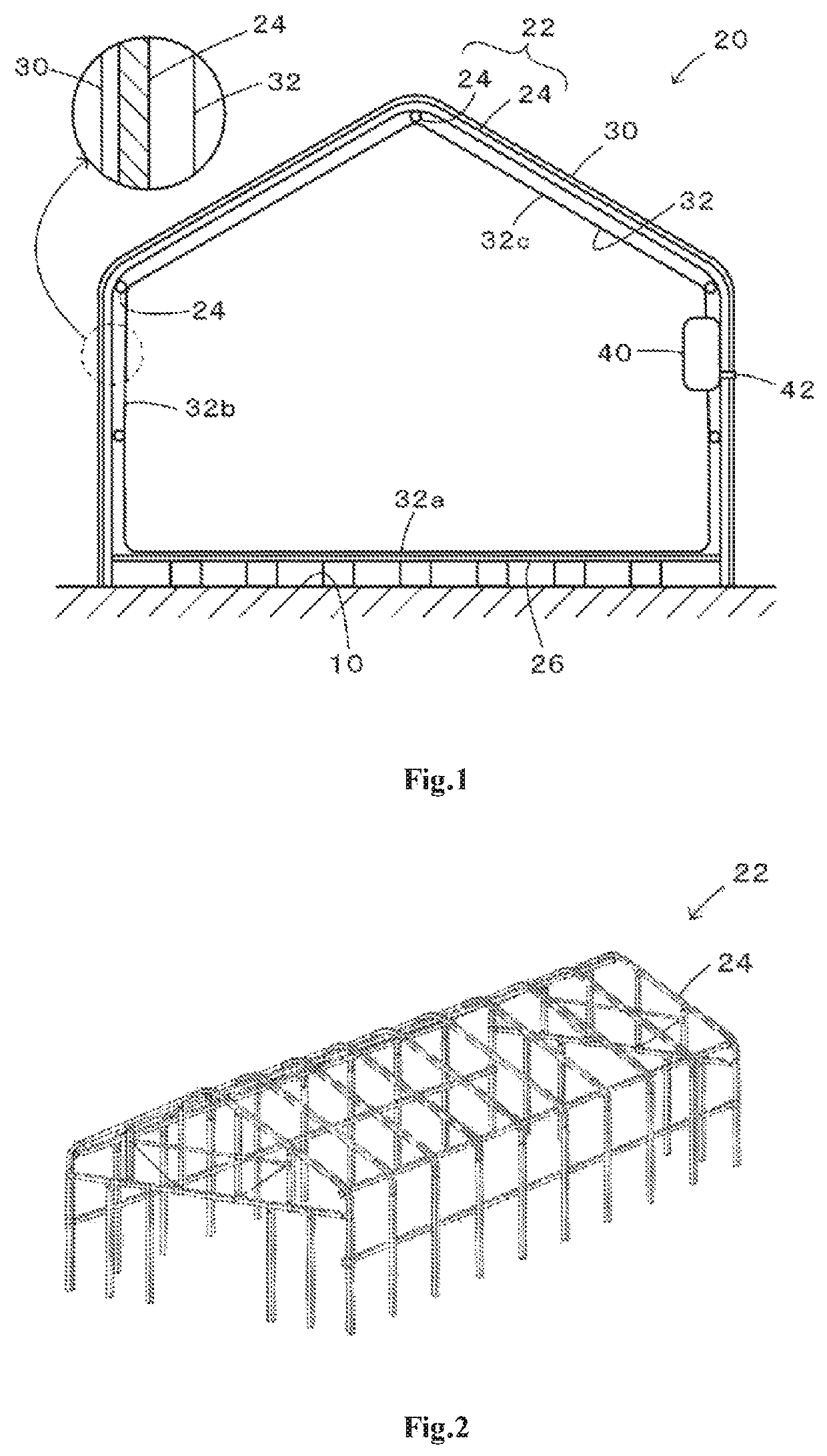
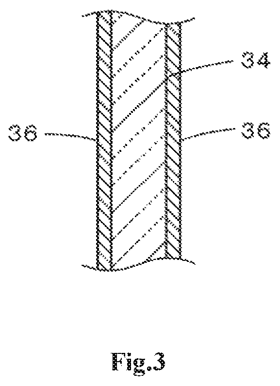
[0014]Next, forms for implementing the present invention are described as follows. FIG. 1 is an explanatory drawing illustrating an outline of a structure of a greenhouse 20 for plant cultivation according to an embodiment of the present invention, FIG. 2 is an appearance structural diagram illustrating an example of a greenhouse framework 22 as a framework structure of the greenhouse 20 for plant cultivation according to the embodiment, and FIG. 3 is an explanatory drawing schematically illustrating an example of a sectional structure of a heat shield sheet.

[0015]As shown in FIGS. 1 and 2, the greenhouse 20 for plant cultivation according to the embodiment includes: a greenhouse framework 22 assembled out of a framework material 24 such as pipes or angles formed from metal (e.g., stainless steel or iron and the like), and fastened to a ground surface 10; a sheet outer surface member 30 configured such that the outer periphery of the greenhouse framework 22 is covered by a plastic s...


PUM

PropertyMeasurementUnit
thicknessaaaaaaaaaa
thicknessaaaaaaaaaa
thicknessaaaaaaaaaa

Abstract

A greenhouse framework (22) is assembled out of a framework material (24) such as typical pipes and the like, and the outer periphery of the greenhouse framework (22) is covered by a sheet outer surface member (30) formed from a plastic sheet; a sheet inner surface member (32) is formed on the inner side of the greenhouse framework (22) in a manner of being spaced by intervals to a certain extent from the sheet outer surface member (30) by using a heat shield sheet such that all of a floor surface (32a), a wall surface (32b), and a ceiling surface (32c) are substantially in a sealed state; and an air conditioning device (40) is installed. Thus, a desirable thermal insulation property is achieved between the inside of the greenhouse and the outside of the greenhouse, and air conditioning can be implemented with high energy efficiency. In other words, a greenhouse for plant cultivation that has a simple configuration and can be air conditioned with high energy efficiency can be provided.

Description

TECHNICAL FIELD[0001]The present invention relates to a greenhouse for plant cultivation, specifically to a greenhouse for plant cultivation formed by covering the outer periphery of a greenhouse framework with a sheet such as a plastic sheet.BACKGROUND[0002]Conventionally, for such greenhouse for plant cultivation, a solution in which a ceiling portion and a wall portion are formed from thermal insulation plates has been proposed (e.g., referring to Patent Document 1). The thermal insulation plate forming the ceiling portion is formed by pasting aluminum foil on both sides of a foaming plate having a thickness of approximately 10 cm, and the thermal insulation plate forming the wall portion is formed by pasting aluminum foil on the inner side of the greenhouse of a foaming plate having a thickness of approximately 20 cm.PRIOR ART DOCUMENT[0003][Patent Document][0004]Patent Document 1: Japanese Patent No. 5595452SUMMARY[0005]However, in the above greenhouse for plant cultivation, a ...

Claims


Application Information

Patent Timeline
Patent Type & Authority Patents(United States)
IPC IPC(8): A01G9/14D06M11/83A01G9/24
CPCD06M11/83A01G9/1415A01G9/1438A01G9/246A01G2009/1453Y02P60/147Y02A40/268Y02A40/252Y02A40/25Y02P60/14A01G9/20A01G9/24B32B15/14B32B2255/205B32B2255/02B32B2410/00
Inventor KAWABATA, SANEYUKIYUKAWA, ATSUYUKISHIMIZU, SHINJI
Owner THE UNIV OF TOKYO
Learn More