Ultrasonic phased array probe using PCB as matching layer

a phased array, ultrasonic technology, applied in the direction of mechanical vibration separation, instruments, laminating printed circuit boards, etc., can solve the problems of long manufacturing lead times, affecting the reliability of the final product, and high cost, so as to improve product reliability, reduce cost, and simplify the manufacturing process

Active Publication Date: 2020-03-03
OLYMPUS SCI SOLUTIONS AMERICAS
View PDF4 Cites 1 Cited by
  • Summary
  • Abstract
  • Description
  • Claims
  • Application Information

AI Technical Summary

Benefits of technology

[0007]Accordingly, it is a general objective of the present disclosure to mitigate the problems with existing acoustic modules.
[0008]It is a further objective of the present disclosure to reduce the number of layers from four to three, thereby simplifying the manufacturing process, reducing cost and improving product reliability.
[0009]It is a further objective of the present disclosure to bond the backing layer directly to the composite with the two layers in intimate contact, thereby reducing ring-down, improving near-surface resolution and enabling the user to detect flaws closer to the surface of the part being inspected.
[0010]It is a further objective of the present disclosure to have a simplified and robust manufacturing method which enhances the manufacturability, reliability and utility of the final product.
[0011]According to the present disclosure, the number of layers of the acoustic module is reduced by eliminating the separate matching layer of existing practice, and instead using a layer which combines the functions of both flexible circuit, preferably in the form of a PCB, and matching material.

Problems solved by technology

A first problem is related to the number of layers and the number of steps in the manufacturing process, both of which lead to high cost and long manufacturing lead times. In addition, the large number of layers impacts reliability of the final product because failure of glue joints between layers is a commonly known reliability problem.
A further problem with the acoustic module in existing practice is that the presence of the flexible circuit results in a lack of intimate contact between the composite and the backing material.
This lack of intimate contact reduces the effectiveness of the backing material, resulting in increased ringing during ultrasonic emission and consequent loss of near-surface resolution.

Method used


Image

  • Ultrasonic phased array probe using PCB as matching layer
  • Ultrasonic phased array probe using PCB as matching layer
  • Ultrasonic phased array probe using PCB as matching layer

Examples


Embodiment Construction

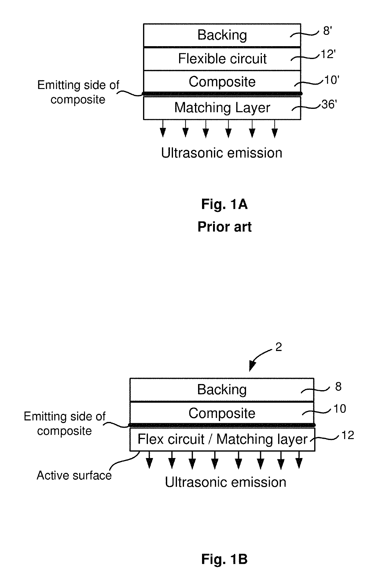
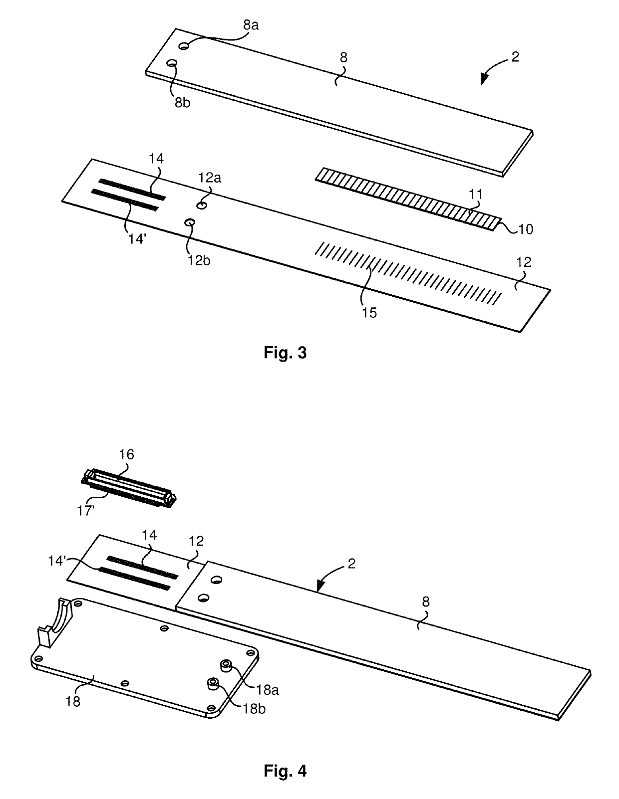
[0020]It should be noted that, unlike existing practice, the assembly steps described in connection with FIGS. 3˜5 below do not include a separate matching layer within acoustic module 2. This is an important and innovative aspect of the present invention. The difference between existing practice and the present invention is further highlighted in FIGS. 1A and 1B.

[0021]FIG. 1A schematically shows existing practice, in which there are four separate layers. A composite 10′ is attached to a flexible circuit 12′ on the non-emitting side of composite 10′. A backing material 8′ is then attached to flexible circuit 12′ to prevent emission from that side of the acoustic module and to damp the ultrasonic elements. A separate matching layer 36′ is attached to the emitting side of composite 10′ to prevent unwanted reflections.

[0022]In contrast, as shown schematically in FIG. 1B, an acoustic module 2 according to the present disclosure comprises only three separate layers. Unlike existing pract...


PUM

PropertyMeasurementUnit
reflected energyaaaaaaaaaa
piezoelectricaaaaaaaaaa
acoustic impedanceaaaaaaaaaa

Abstract

Disclosed is a flexible ultrasonic transducer in which a single layer serves dual function as both a matching layer and a flexible circuit for making electrical connections, and there is no separate matching layer. Also disclosed is a method of assembling the flexible transducer.

Description

CROSS-REFERENCE TO RELATED APPLICATIONS[0001]This application claims the benefit and priority of U.S. Provisional patent application Ser. No. 62 / 301,115 filed Feb. 29, 2016 entitled FLEXIBLE ARRAY USING A FLEXIBLE CIRCUIT AS THE MATCHING LAYER, the entire disclosure of which is incorporated herein by reference.FIELD OF THE INVENTION[0002]The invention relates to manufacture of flexible ultrasonic probe array transducers for non-destructive testing / inspection (NDT / NDI), more specifically to an ultrasonic phased array probe using a printed circuit board (PCB) directly as its matching layer.BACKGROUND OF THE INVENTION[0003]Flexible probe array transducers are commonly used for ultrasonic inspection of tubes, pipes or other curved surfaces. The flexible array often comprises a long ribbon-like acoustic module which is wrapped around the tube or pipe for detecting, for example, thickness variation in tubes, and / or cracks in pipes or welds.[0004]The acoustic module usually comprises four ...

Claims


Application Information

Patent Timeline
Patent Type & Authority Patents(United States)
IPC IPC(8): B06B1/06G01N29/26G01N29/32G01N29/24H05K1/11H05K1/02H01L41/09H01L41/22H05K1/03
CPCG01N29/245G01N29/262H05K1/111H05K1/03B06B1/0622H05K1/028G01N29/32H05K2201/0104H05K1/0393H05K3/0058H05K2201/10083
Inventor LIU, SHENGKELLER, RONALD
Owner OLYMPUS SCI SOLUTIONS AMERICAS
Why Eureka
Try Eureka