Control system

a control system and control circuit technology, applied in the direction of electrical equipment, electrical variable regulation, instruments, etc., can solve the problems of unfavorable meaningful protection against failure, unlit signals, unfavorable safety conditions in signalling circuits, etc., to improve reliability, availability and maintainability, and high integrity

Active Publication Date: 2020-03-03
KHOSLA AARTI +1
View PDF9 Cites 0 Cited by
  • Summary
  • Abstract
  • Description
  • Claims
  • Application Information

AI Technical Summary

Benefits of technology

[0043]The object of the present invention is to provide an improved control system with high level of integrity for system operation monitoring, remote networking and control, improvement in reliability, availability and maintainability, simultaneously reducing costs, increasing energy efficiency and savings.
[0045]Another object of the present invention is to logically integrate the units, sub-units and / or functions of the system in a sequence which improves the safety of operation in line with the objects of the invention and terms of reference thereby also reducing the need of the components and materials used.
[0088]Still another embodiment of the present invention provides a system, wherein the driven unit (26) comprises of redundancy and reliability, at least two LED Arrays each with independent current limiting means (2b, 2c, 2d, 62) so that failure of one current limit circuit will not affect other LED array.

Problems solved by technology

While such devices have their uses, the use of such devices can itself result in unsafe conditions in the signalling circuits due to leakage, partial failure and the like.
Leakage in such devices results in the current being drawn by the leakage resulting in the LED's not being lit, while simulating a lit up signal.
However, without an overall feedback system, meaningful protection against failure is not feasible.
However, this can result in reduction in the intensity of the beam.
Also, in a condition where more than one LED has failed, a condition of poor visibility and / or unsafe conditions are created, since the shunts may be drawing current, but the LED cluster is not emitting adequate light.
This, however, requires substantial power dissipation in the shunt resistances.
However, the heat builds up in the enclosure over a period of time thereby affecting its performance.
There can be a partial failure which may further lead to a complete failure.
It is not desirable to have blanking of signals or unwanted signal lit.

Method used


Image

  • Control system
  • Control system
  • Control system

Examples


Embodiment Construction

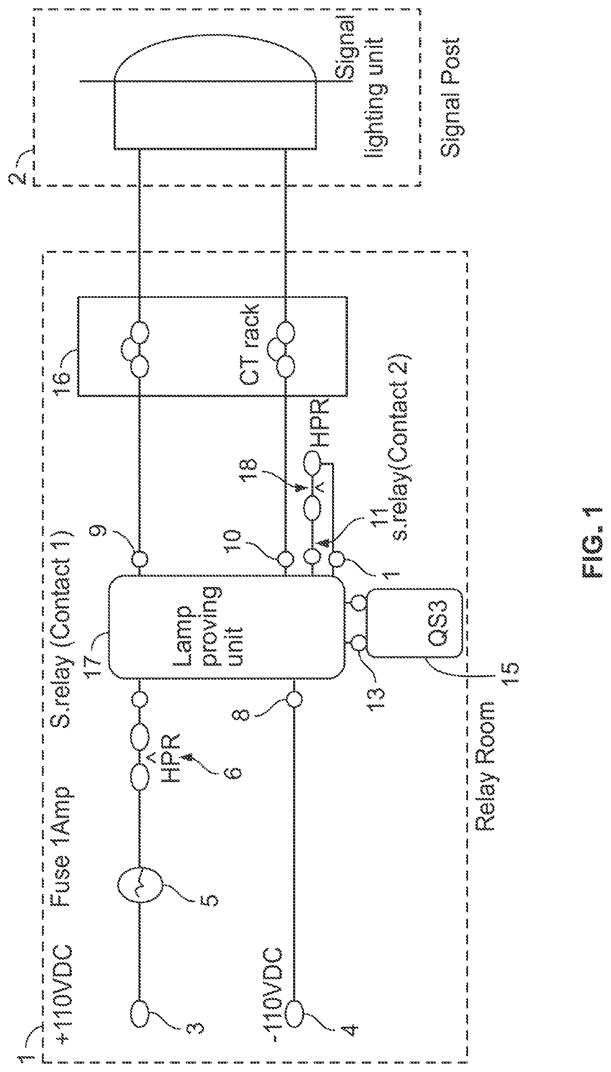
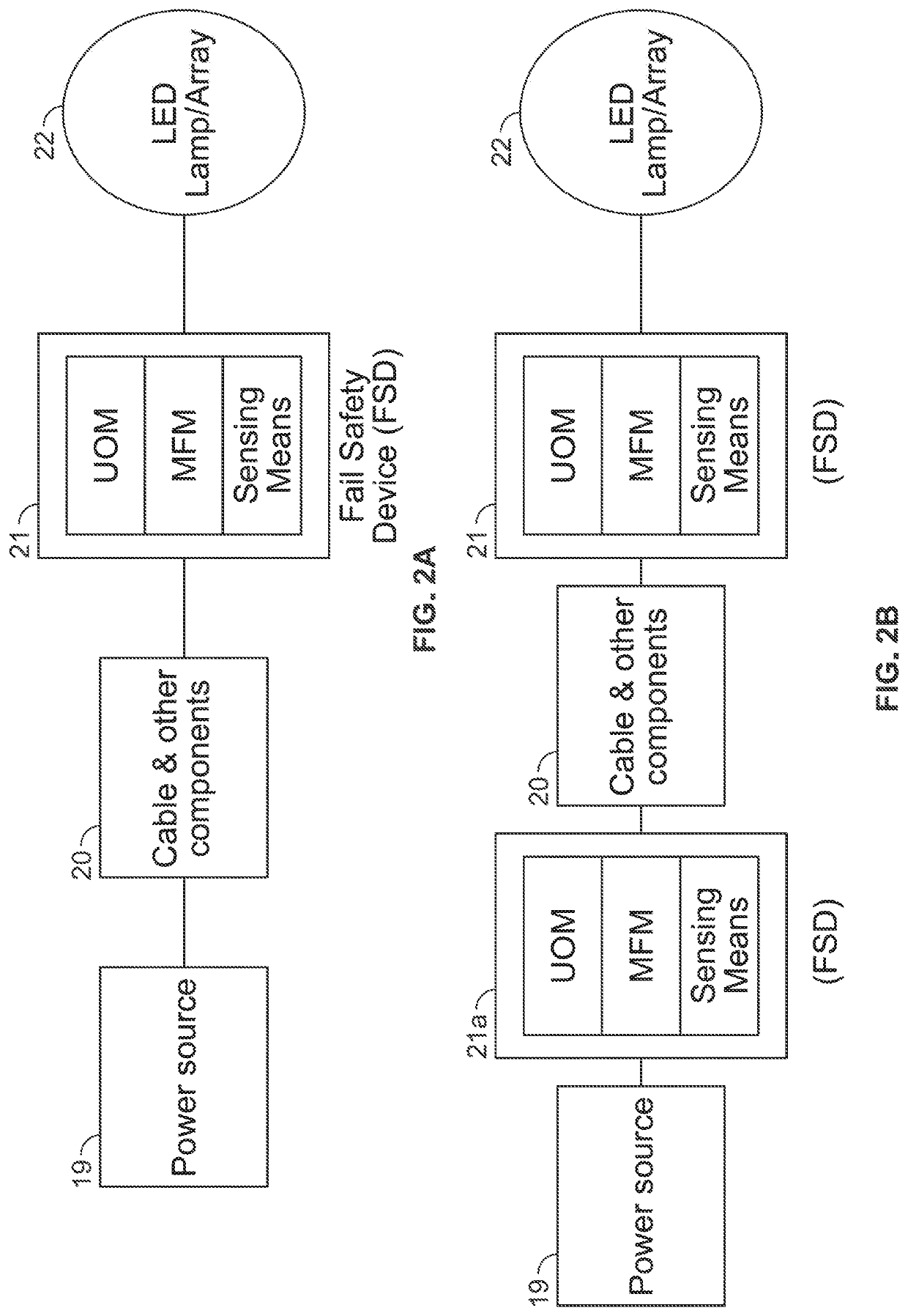
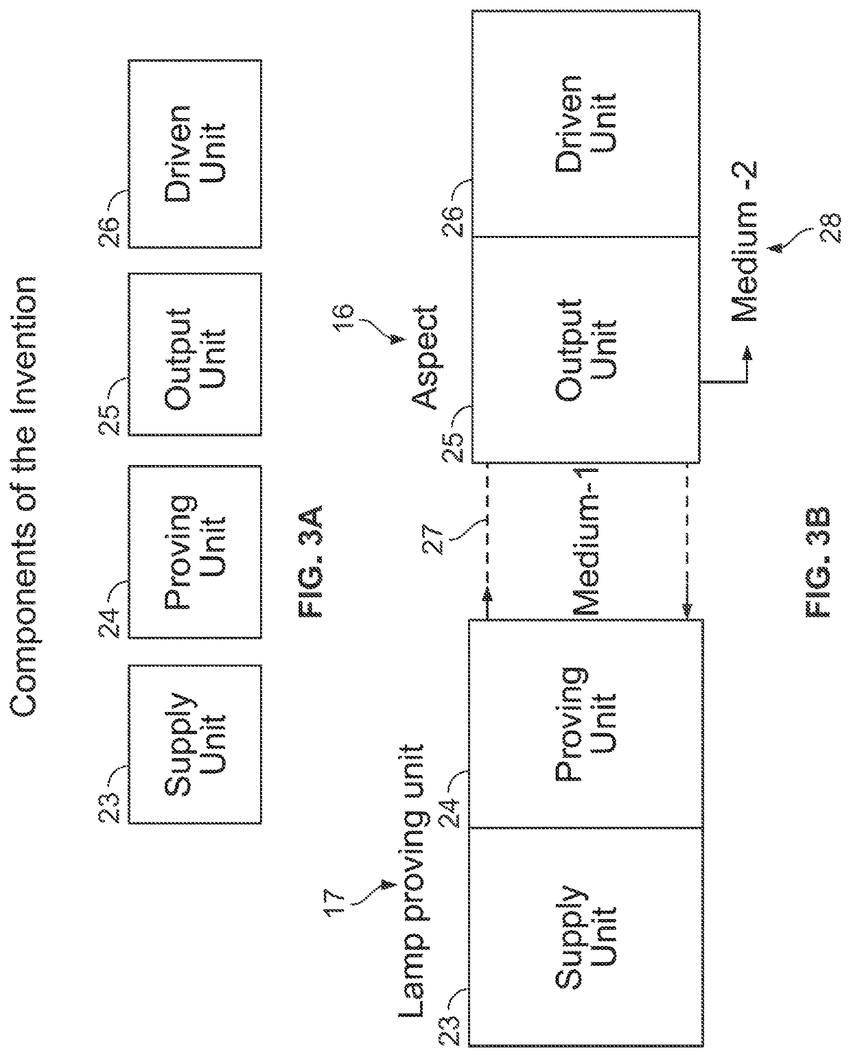
[0111]The present invention relates to an improved control system and is illustrated for signalling lamp systems with one or more driven unit comprising of plurality of LED cluster lamps, said system comprising at least one power source, connected to at least one supply unit optionally with at least one proving unit on one side of at least one connecting medium, at least one output unit connected to at least one driven unit connected to the other side of the said at least one connecting medium, the system requiring at least one monitored and / or control function with at least one term of reference, the said function being in different domain from the at least one monitored, wherein one or any unit of the said improved control system may consist of driven unit consisting of LED cluster lamp, but is not restricted only to LED cluster lamp.

[0112]Some of the terms such as “terms of reference”, “monitoring and control function”, “Driven Unit driving”“Driven Unit Immunity” are explained he...


PUM


Abstract

The present invention relates to an improved control system for use in applications requiring high level of functional integrity at one or more location, for improving efficiency, availability, reliability and safety of operation in various applications by segregating the domains of various functions critical to maintain high level of system operation integrity, remote networking and control, and transporting a proven, monitored function through a medium to another location and using the received proven function information to further prove the function at the receiving location with the functional identification of the receiving location, entire operation being online and / or periodically reciprocated / handshake / monitored.

Description

RELATED APPLICATION[0001]This application is a national phase entry under 35 USC 371 of International Patent Application No.: PCT / IB2016 / 000466 filed on 14 Apr. 2016, which claims priority from Indian Application No. 1047 / DEL / 2015 filed on 15 Apr. 2015, the disclosures of which are incorporated in their entirety by reference herein.FIELD OF THE INVENTION[0002]The present invention relates to an improved control system for use in applications requiring high level of functional integrity at one or more locations. When operated on a product application said system causes improvement in efficiency, availability, reliability and safety of operation by segregating the domains of various functions critical to maintain high level of system operation integrity, remote networking & control, and transporting a proven, monitored function through a medium to another location. Said system uses the received proven function information to further prove the function at the receiving location with th...

Claims


Application Information

Patent Timeline
Patent Type & Authority Patents(United States)
IPC IPC(8): G05F1/00H05B41/36H05B33/08H05B39/04H05B44/00
CPCH05B45/22H05B45/20
Inventor KHOSLA, AARTIKHOSLA, SANJEEV
Owner KHOSLA AARTI
Why Eureka
Try Eureka