
Particle sensing device and electronic apparatus having the same

a technology of electronic equipment and sensing device, which is applied in the direction of suspension and porous material analysis, instruments, material analysis, etc., can solve the problems of serious deterioration of air quality and visibility, large amount of particulate matter, and long time-consuming and labor-intensive air quality, and achieves the effect of easy integration into various fields

Active Publication Date: 2020-03-10
WINBOND ELECTRONICS CORP
View PDF13 Cites 0 Cited by
  • Summary
  • Abstract
  • Description
  • Claims
  • Application Information

AI Technical Summary

Benefits of technology

The patent provides a particle sensing device that can detect the sizes of particles in the environment. This device can be easily integrated into various electronic devices and is designed to measure the density of particulate matter in the air. The device uses a 3D stacking electrode design with multiple electrode pairs to determine the particle sizes. This technology can be miniaturized for use in portable electronic devices and is manufacturable with existing technology.

Problems solved by technology

Because particle sizes of the particulate matters are very small, the particulate matters can stay in the atmosphere for a very long time and travel for a very long distance.
As a result, the particulate matters can lead to serious deterioration on air quality and visibility.
The particulate matters can absorb a large amount of toxic and hazardous substances.
In other words, the particulate matters can severely affect human health.
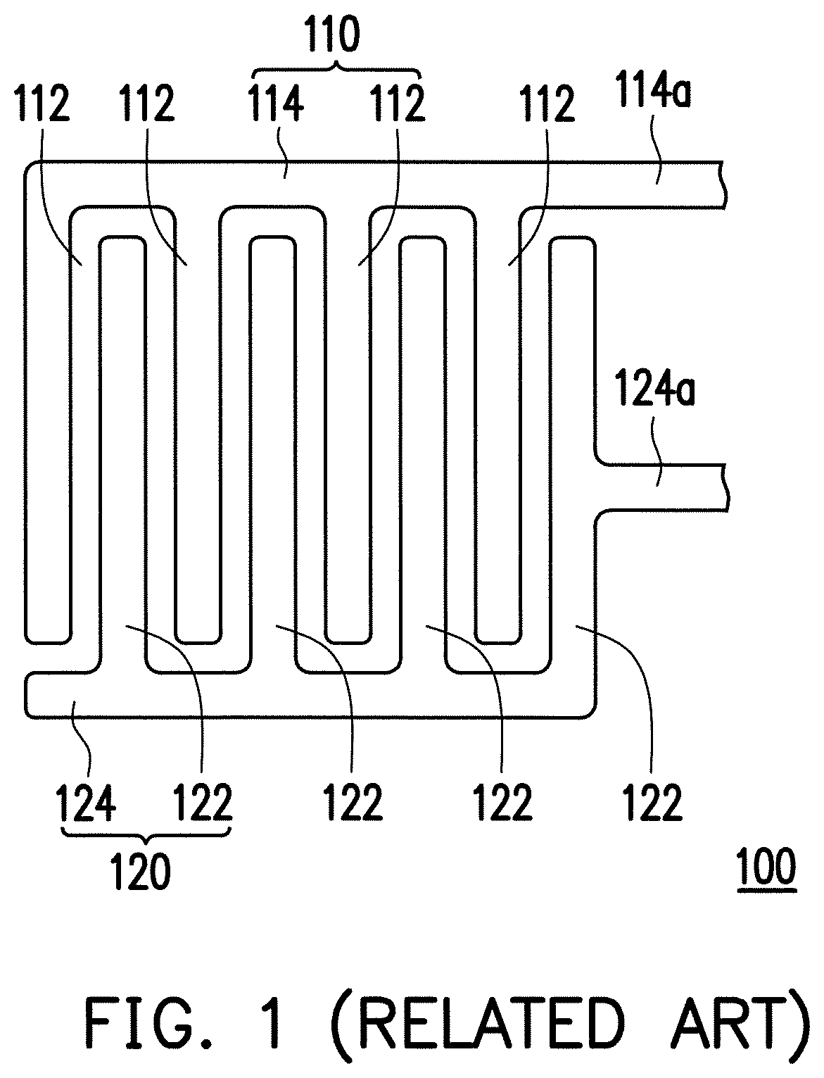
However, the capacitive-type particle sensor 100 in conventional art is extremely sensitive to ambient temperature, moisture in the air, etc.
Besides, due to a poor recognition capability for the particle sizes, the capacitive-type particle sensor 100 in conventional art can only measure increase or decrease in a particle amount, relatively.

Method used


Image

  • Particle sensing device and electronic apparatus having the same
  • Particle sensing device and electronic apparatus having the same
  • Particle sensing device and electronic apparatus having the same

Examples


Embodiment Construction

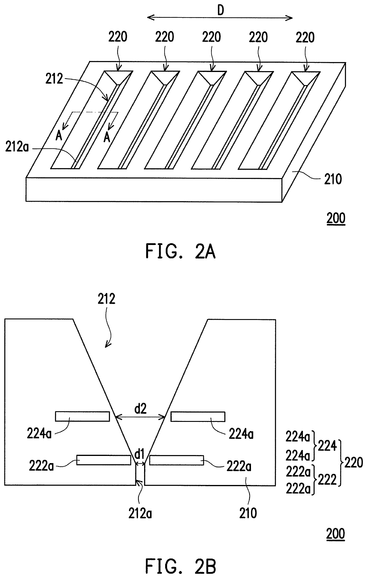
[0027]FIG. 2A is a three-dimensional view of a particle sensing device according to an embodiment of the disclosure. FIG. 2B is a cross-sectional view of the particle sensing device of FIG. 2A taken along a sectional line A-A. FIG. 2A and FIG. 2B illustrate the condition before particulate matters P enter the particle sensing device. Please referring to FIG. 2A and FIG. 2B, a particle sensing device 200 may include a substrate 210 and at least one particle sensing element 220. The substrate 210 has at least one groove 212. In this embodiment, particle sensing elements 220 and grooves 212 are provided. A through hole 212a is disposed at a bottom of each groove 212. The through hole 212a penetrates a bottom of the substrate 210.

[0028]The particle sensing element 220 is disposed in the substrate 210. Herein, the particle sensing element 220 may include a first electrode pair 222 and a second electrode pair 224. Two first sub-electrodes 222a of the first electrode pair 222 are disposed ...


PUM

PropertyMeasurementUnit
distanceaaaaaaaaaa
distanceaaaaaaaaaa
distanceaaaaaaaaaa

Abstract

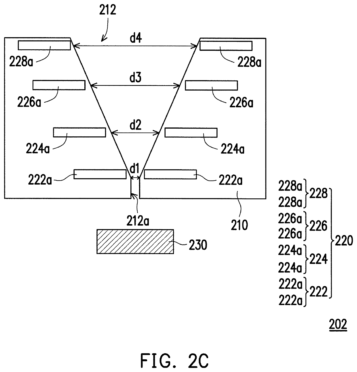
A particle sensing device, including a substrate and at least one particle sensing element, is provided. The substrate has a groove, and a through hole is disposed at a bottom of the groove. The through hole penetrates a bottom of the substrate. The particle sensing element is disposed in the substrate. The particle sensing element may include a first electrode pair and a second electrode pair. Two first sub-electrodes of the first electrode pair are disposed nearby two sides of the groove, respectively. And, a first distance is provided between the two first sub-electrodes. Two second sub-electrodes of the second electrode pair are disposed nearby two sides of the groove, respectively. And, a second distance is provided between the two second sub-electrodes. The first distance is smaller than the second distance.

Description

CROSS-REFERENCE TO RELATED APPLICATION[0001]This application claims the priority benefit of China application serial no. 201610235833.5, filed on Apr. 15, 2016. The entirety of the above-mentioned patent application is hereby incorporated by reference herein and made a part of this specification.BACKGROUNDTechnical Field[0002]The disclosure relates to a particle sensing device, and more particularly, relates to a particle sensing device and an electronic apparatus having the particle sensing device, which are capable of sensing the particulate matter (PM) in the air.Description of Related Art[0003]In recent years, owing to the rising awareness of environment protection, people have gradually paid more attention to air quality in the living environment. The particulate matter refers to a mixture of particles and droplets, and serves as a pollutant standard index. Because fine particles with diameter less than or equal to 10 micrometer (μm) can enter the lung through the nose and the ...

Claims


Application Information

Patent Timeline
Patent Type & Authority Patents(United States)
IPC IPC(8): G01N15/06G01N27/22G01N15/00G01N33/00G01N15/10
CPCG01N15/0656G01N15/0606G01N27/22G01N15/1031G01N33/0036G01N2015/0046G01N15/02
Inventor HO, YU-HSUANWU, YI-DER
Owner WINBOND ELECTRONICS CORP
Learn More