Method for improving signal to noise ratio in an uplink transmission

a signal to noise ratio and transmission method technology, applied in the field of network systems, can solve the problems of higher interference or noise level in any network system, poor signal quality, error, etc., and achieve the effect of improving signal to noise ratio and computing signal to noise ratio (snr)

Active Publication Date: 2020-03-10
MURALIDHAR KARTHIK
View PDF8 Cites 0 Cited by
  • Summary
  • Abstract
  • Description
  • Claims
  • Application Information

AI Technical Summary

Benefits of technology

[0009]In an aspect, a method is provided for improving signal to noise ratio in an uplink transmission. The method includes determining a plurality of combinations of “N” possible users to be selected among “X” users that are transmitting signals to a base station comprising “n” number of antennas, where n>=N, wherein selected “N” users transmit on a same sub-carrier; computing signal to noise ratio (SNR) of the signals received from each of the users among the determined combination of “N” possible users; and selecting at least one combination among the plurality of combinations of “N” possible users, such that, a combined signal to noise ratio of the selected combination is maximum among all combinations.
[0010]In another aspect, a method is provided for improving signal to noise ratio in an uplink transmission. The method includes receiving signals from “X” users at a plurality of antennas present in a plurality of base stations; determining a plurality of combinations of “N” possible users to be selected among the “X” users, wherein each of the “N” users is associated with one base station, such that each of the “N” users transmit to all the base stations, each comprising at least “n” number of antennas, where n>=N, wherein each of the “N” users transmit on a same sub-carrier; computing signal to noise ratio for each of the users among the determined combinations of “N” possible users by using signals received by all the antennas of all the base stations; and selecting at least one combination among the plurality of combinations of “N” possible users, such that, a combined signal to noise ratio of the selected combination is maximum among all combinations.
[0011]In yet another aspect, a method is provided for improving signal to noise ratio in an uplink transmission. The method includes receiving signals from “X” users, each of the “X” users comprising two antennas, at a plurality of antennas present in a plurality of base stations; determining a plurality of combinations of “N” possible users to be selected among the “X” users, wherein each of the “N” users is associated with one base station, such that each of the “N” users transmit to all the base stations, each comprising at least “n” number of antennas, where n>=N, wherein each of the “N” users transmit on a same sub-carrier; computing signal to noise ratio for each of the users among the determined combinations of “N” possible users; and selecting at least one combination among the plurality of combinations of “N” possible users, such that, a combined signal to noise ratio of the selected combination is maximum among all combinations.

Problems solved by technology

As SNR decreases, the quality of the signal gets poorer which means higher interference or noise level in any network systems.
As SNR goes lower, the probability of error goes higher leading to poor network throughput.
Traditionally, signals from one user in one subcarrier face interference from the signals from the other users in the same subcarrier which decreases the network throughput of the wireless network systems.
Although, it enables far high data rates to be achieved but ends up adding complexity to the system in terms of processing and the number of antennas required.

Method used


Image

  • Method for improving signal to noise ratio in an uplink transmission
  • Method for improving signal to noise ratio in an uplink transmission
  • Method for improving signal to noise ratio in an uplink transmission

Examples


Embodiment Construction

[0034]I. OVERVIEW[0035]II. EXEMPLARY SYSTEM[0036]III. FIRST EXEMPLARY METHOD FOR IMPROVING SNR-1 CELL, 1 BS, MANY USERS ON SAME SUB-CARRIER, 1 ANTENNA / USER[0037]IV. SECOND EXEMPLARY METHOD FOR IMPROVING SNR-N CELL, N BS, 1 USER / BS ON A GIVEN SUB-CARRIER, 1 ANTENNA / USER[0038]V. THIRD EXEMPLARY METHOD FOR IMPROVING SNR-N CELL, N BS, 1 USER / BS ON A GIVEN SUB-CARRIER, 2 ANTENNA / USER[0039]VI. ACCOMMODATING MORE USERS IN A CELL ON THE SAME SUB-CARRIER[0040]VII. SELECTING BEST USERS FOR ACCOMMODATING IN A CELL ON THE SAME SUB-CARRIER[0041]VIII. COMPUTING SIGNAL TO NOISE RATIOS[0042]IX. ANTENNA SELECTION FOR IMPROVING SNR[0043]X. CHANNEL ESTIMATION[0044]XI. CONCLUSION

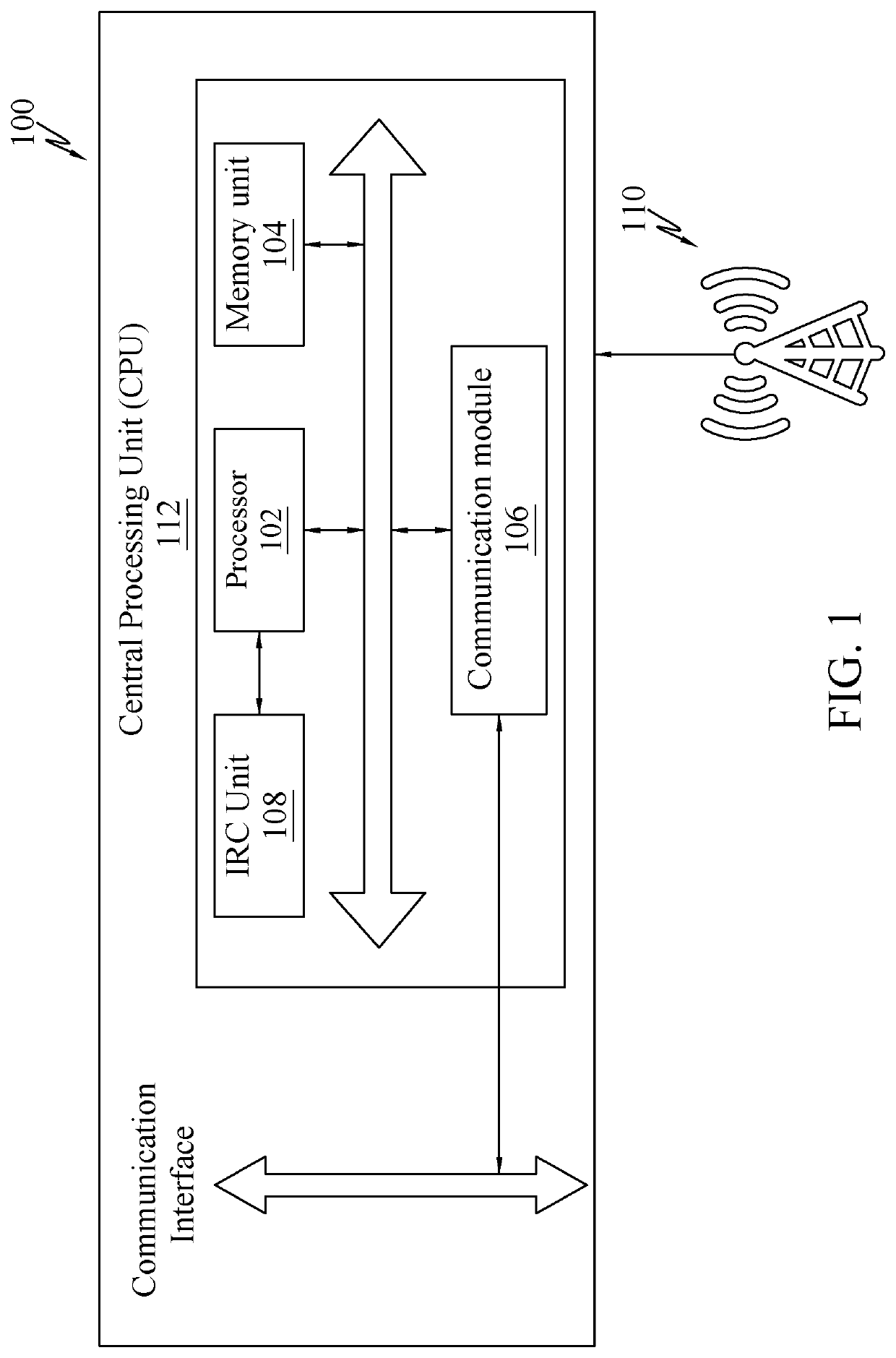
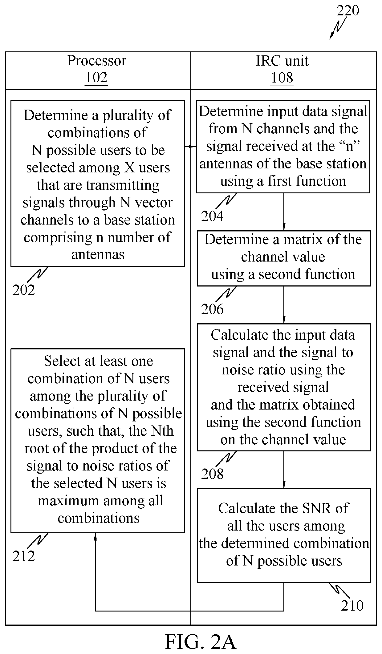
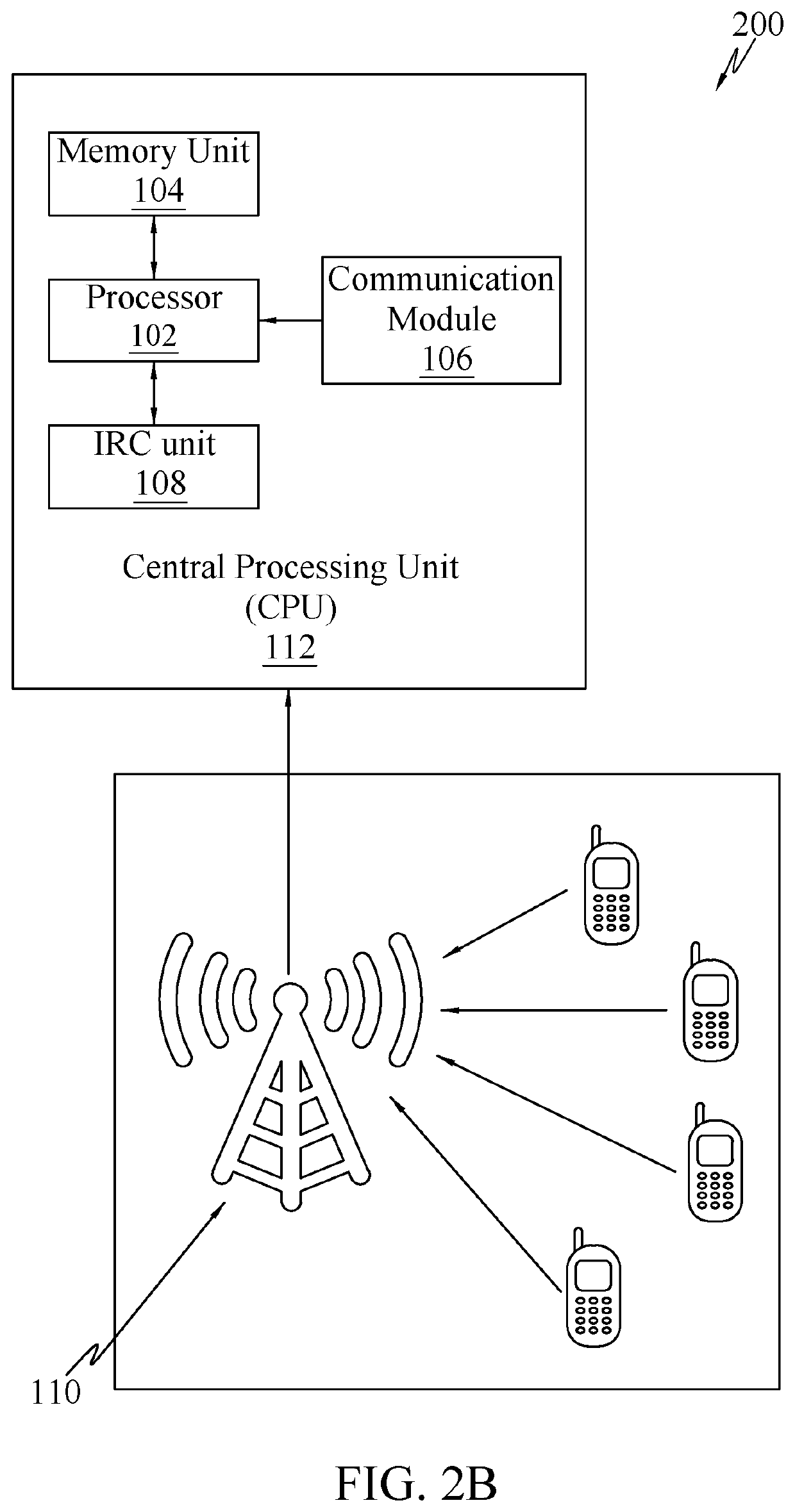
[0045]The following detailed description includes references to the accompanying drawings, which form part of the detailed description. The drawings show illustrations in accordance with example embodiments. These example embodiments are described in enough detail to enable those skilled in the art to practice the present subje...


PUM


Abstract

A method for improving signal to noise ratio in an uplink transmission. The method includes determining a plurality of combinations of “N” possible users to be selected among “X” users that are transmitting signals to a base station comprising “n” number of antennas, where n>=N, wherein selected “N” users transmit on a same sub-carrier; computing signal to noise ratio (SNR) of the signals received from each of the users among the determined combination of “N” possible users; and selecting at least one combination among the plurality of combinations of “N” possible users, such that, a combined signal to noise ratio of the selected combination is maximum among all combinations.

Description

BACKGROUND[0001]Unless otherwise indicated herein, the materials described in this section are not prior art to the claims in this application and are not admitted to being prior art by inclusion in this section.Field[0002]The subject matter in general relates to LTE network systems. More particularly, but not exclusively, the subject matter is directed to reduction of interference and improvement of signal strength in an LTE system.Discussion of Related Art[0003]Long-Term Evolution (LTE) is standard for high-speed wireless communication for mobile phones. It increases the capacity and speed using different radio interface together with core network improvements. In LTE, new technologies have recently been adapted where there is co-operation between base station and the user signals received by these base stations are processed by a Central Processing Unit (CPU). Pertaining to cellular networks, the radio uplink is the transmission path from the mobile station (cell phone) to a base...

Claims


Application Information

Patent Timeline
Patent Type & Authority Patents(United States)
IPC IPC(8): H04B1/04H04B1/62H04B1/10H04J11/00H04B17/336H04B1/7107H04B7/0456H04W72/12
CPCH04B1/71075H04B7/0456H04B17/336H04J11/003H04B1/0475H04B1/10H04B1/62H04W72/121
Inventor MURALIDHAR, KARTHIK
Owner MURALIDHAR KARTHIK
Why Eureka
Try Eureka