Fluid monitoring apparatus including fluid density detection system for subsea apparatus

a technology of fluid density detection and monitoring apparatus, which is applied in the direction of measurement devices, structural/machine measurement, instruments, etc., can solve problems such as preventing them from functioning, and achieve the effects of reliable, robust and accurate, effective and reliabl

Active Publication Date: 2020-03-17
EQUINOR ENERGY AS
View PDF4 Cites 0 Cited by
  • Summary
  • Abstract
  • Description
  • Claims
  • Application Information

AI Technical Summary

Benefits of technology

[0030]The first fluid may be sea water, the second fluid may be oil, e.g. crude oil, and the third fluid may be gas, e.g. natural gas. The floats may hence be provided with respective densities that are between the density of oil and water, for the first float, and between the density of water and gas, for the second float. The present invention is particularly advantageous in the field of oil and gas production. The present invention can detect leaks of both oil and gas, and can differentiate between the two, in subsea locations. Further, it is possible for the apparatus to be installed into a subsea cap or the like. Such a cap may be located and configured such that rising fluid (e.g. oil / gas) may be trapped within the cap. This could lead to dangerously large pressures of gas building up. To avoid this, the venting function of the invention allows for the gas to vent. Thus, oil and gas leaks can be detected. The oil can be contained, whilst gas leaks can be vented.
[0031]The fluid monitoring apparatus of the present invention may be particularly reliable, robust and accurate when the fluids are sea water, oil and gas. The densities of sea water and oil and gas are all quite different. The inventors have recognised that using the principles of buoyancy instead of the prior-known electrode system provides a much more effective and reliable monitor for sea water, oil and gas in particular.
[0032]Of course, whilst these advantages are particularly apparent in the field of oil and gas, it should be understood that preventing building up of certain fluids, whilst containing other fluids, can be advantageous in other fields as well.
[0033]An advantage of one of the example embodiments of the invention is that it can allow for both the detection of the first and second fluid replacing the less dense third fluid, and also for the selective draining of the denser first fluid.
[0034]The first float and / or the second float may comprise an end portion and a rod portion. The rod portions of the first and second floats may both pass at least partially through the passageway. The / each end portion may be orientated perpendicularly to the rod portions. The / each end portion may comprise a planar portion that is orientated perpendicularly to the axis of the / each rod portion. The end portion of the first and / or second float may be shaped such that it may seal the passageway.

Problems solved by technology

These have the disadvantage, however, of gathering salts around the electrodes that affect their performance and eventually prevent them from functioning.

Method used


Image

  • Fluid monitoring apparatus including fluid density detection system for subsea apparatus
  • Fluid monitoring apparatus including fluid density detection system for subsea apparatus

Examples


Embodiment Construction

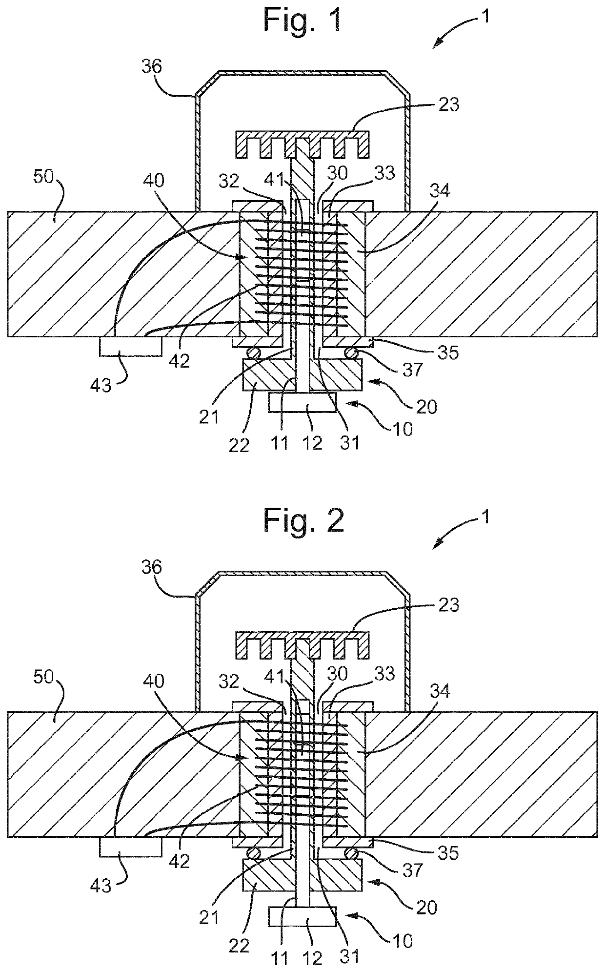
[0089]Regarding FIG. 1, a fluid monitoring apparatus 1 is shown. The fluid monitoring apparatus comprising a first float 10 and a second float 20. The first float 10 has a density less than that of sea water but greater than that of crude oil. The second float 20 has a density less than crude oil but greater than that of natural gas. In FIG. 1, sea water is present in the vicinity of fluid monitoring apparatus 1 so both the first float 10 and the second float 20 are floating in their first positions, which are their upper most positions in this embodiment.

[0090]The first float 10 comprises a rod portion 11 and a disc-shaped end portion 12. The rod portion 11 and the end portion 12 are concentric.

[0091]The diameter and thickness of the end portion 12 of the first float 10 is less than the diameter and thickness of the end portion 22 of the second float 10.

[0092]The second float 20 comprises a rod portion 21 and a disc-shaped end portion 22. The rod portion 21 and the end portion 22 a...


PUM

PropertyMeasurementUnit
diameteraaaaaaaaaa
diameteraaaaaaaaaa
diameteraaaaaaaaaa

Abstract

Subsea equipment-protection apparatus including a fluid monitoring apparatus for detecting a first fluid, a second fluid and a third fluid. The fluid monitoring apparatus including a first float having a density less than that of the first fluid but greater than that of the second fluid; a second float having a density less than that of the second fluid but greater than that of the third fluid; and a sensor configured to detect the first and second floats so that the position of the floats can be determined. The first float floating when a fluid with density greater than the first float is present and sinking when a fluid with density less than the first float is present. The second float floating when a fluid with a density greater than the second float is present and sinking when a fluid with a density less than the second float is present.

Description

BACKGROUND OF THE INVENTION1. Technical Field[0001]The invention relates to a fluid monitoring apparatus.[0002]It is important in many types of industry, for example in the oil and gas industry, to be able to monitor what fluids are present in a system. For example, in the oil and gas industry, in the vicinity of subsea equipment sea water is typically present. However, during leaks, hydrocarbons such as oil and gas may leak into the surrounding environment. It is desirable to detect such leaks.2. Description of the Related Art[0003]Previous methods of detecting such leaks have included using a monitoring apparatus that includes electrodes that can detect whether sea water, oil or gas is present. These have the disadvantage, however, of gathering salts around the electrodes that affect their performance and eventually prevent them from functioning. It is therefore desirable to provide a more reliable and robust apparatus.SUMMARY OF THE INVENTION[0004]The present invention provides a...

Claims


Application Information

Patent Timeline
Patent Type & Authority Patents(United States)
IPC IPC(8): G01F23/28G01M3/32G01F23/38G01N9/18G01N9/12G01F23/72G01F23/76
CPCG01F23/38G01N9/18G01M3/3245G01N9/12G01F23/72G01F23/76
Inventor GRYTDAL, IDAR OLAV
Owner EQUINOR ENERGY AS
Why Eureka
Try Eureka