Arthroscopic shoulder arthroplasty and method thereof

a shoulder arthroplasty and arthroscopic technology, applied in the field of patient specific shoulder implants, can solve the problems of significant surgical exposure, unduly damage local anatomical structures, rotator cuff and supporting structures, etc., and achieve the effect of facilitating the extraction of the head and minimizing damage to the surrounding muscles and supporting ligaments and tissues

Active Publication Date: 2020-03-24
JOINT INNOVATION TECH LLC
View PDF12 Cites 2 Cited by
  • Summary
  • Abstract
  • Description
  • Claims
  • Application Information

AI Technical Summary

Benefits of technology

[0004]The purpose of the present invention is to present a novel method and surgical technique providing improved instrumentation for insertion of total shoulder implant components arthroscopically. Therefore, minimizing damage to the surrounding muscles and supporting ligaments and tissues. Therefore, the object of this invention is to provide a surgical method for insertion of the humeral and glenoid implant components using arthroscopic techniques using stab wounds and minimal surgical incision. Minimal incisions are used to perform the initial steps of the procedure. An arthroscope is introduced superiorly and laterally in the usual conventional technique to visualize the anterior surface of the proximal humerus. Initially the humeral head is transected, which will debulk the joint and provide a working space into the shoulder joint. An external cutting guide having a slot of 50° inclination is secured to the humerus using a pin inserted percutaneously below the surgical neck of the humerus. Said external guide is aligned along the anterior surface of the arm. A mini-reciprocating saw is inserted anteriorly through a small anterior skin incision and passed through the guiding slot of the external guide and osteotomy of the head is carried out. To facilitate the extraction of the head, it can be fragmented and removed in pieces. A reciprocation saw, or high-speed burr may be used for the fragmentation under direct arthroscopic visualization. These tools are redesigned for use through the slotted guide. In the preferred embodiment of this invention, the glenoid component is metallic. The glenoid component having a rimmed metallic base to be attached to the reamed and prepared glenoid surface with a central peg and two large cancellous screws. The polished metallic articular glenoid component will be subsequently snapped in and secured in the recess of glenoid base plate by multiple locking tabs.

Problems solved by technology

Damages to the rotator cuff and supporting structures will require the use of reverse shoulder implant, where the geometry of the components is reversed, and the humeral component is designed as a cupule while the hemispherical ball is attached to the glenoid plate.
However, the surgical procedure for the insertion of the prosthetic component requires significant surgical exposure that will unduly damage local anatomical structures such as surrounding muscles and adjacent tendon tendons.
Said damage will impose longer healing period and require extensive postoperative physical therapy.
However, the existence of prior trauma and deformity of the proximal humerus preclude the use of implant with humeral stem.
More recently, stem free or stemless humeral component are designed and used but remain bulky and require insertion through a conventional extensive surgical approach.
Conventionally used glenoid polyethylene components are known to flow and become loose leading to osteolysis.

Method used


Image

  • Arthroscopic shoulder arthroplasty and method thereof
  • Arthroscopic shoulder arthroplasty and method thereof
  • Arthroscopic shoulder arthroplasty and method thereof

Examples


Embodiment Construction

[0030]While the invention is susceptible to different changes and modifications, specific embodiments of the present invention are shown by way of example in the drawings and will be described herein in details.

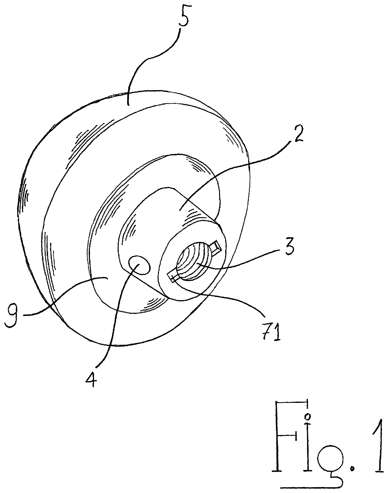
[0031]Referring now to FIG. 1, which depict an embodiment of a humeral implant, which has a cup shape hemispherical articular polyethylene surface 5 and a metallic fixation portion 2. Said metallic portion comprises a central metallic tapered peg 2 at one end, which will be inserted into the humerus and the other end a cylindrical portion that will be slidingly inserted into the recess 6 situated on the flat surface of the polyethylene portion of the humeral head implant. At least two or more Locking tabs 8 will interlock into a circular groove 7 and securely attach the metallic cylinder into the polyethylene head. The metallic portion 2 of the central peg is slightly tapered at 2° to 5° for better retaining into the humeral bone. A circular disc 9 situated between the cylind...


PUM


Abstract

A novel method and instrumentation for insertion of humeral and glenoid total shoulder implant using arthroscopic visualization for bony preparation as well as insertion of components through small incisions. Mini instruments and cannulated guides and reamers are used in order to perform the procedure under direct arthroscopic visualization. For ease of insertion, the components are inserted separately and assembled in situ. Securing the humeral components in place is accomplished with bicortical screw transfixing the central peg of component.

Description

FIELD OF THE INVENTION[0001]The present invention relates to the use of patient specific shoulder implants and in particular to the use of instrumentation and guides for allowing the insertion of the implant component arthroscopically.BACKGROUND OF THE INVENTION[0002]Shoulder joint replacement has been in use for many decades. The articular surfaces of the shoulder joint include a ball and a socket which may be damaged by trauma or degenerative disease. Pain and limitation of movement will require a replacement of the articular surfaces using a hemispherical humeral component and a shallow glenoid component. Damages to the rotator cuff and supporting structures will require the use of reverse shoulder implant, where the geometry of the components is reversed, and the humeral component is designed as a cupule while the hemispherical ball is attached to the glenoid plate.[0003]However, the surgical procedure for the insertion of the prosthetic component requires significant surgical e...

Claims


Application Information

Patent Timeline
Patent Type & Authority Patents(United States)
IPC IPC(8): A61B17/17A61B17/14A61B17/15A61B17/16A61F2/40A61F2/30A61F2/46
CPCA61B17/1659A61B17/144A61B17/1684A61B17/1778A61F2/4612A61F2/4081A61F2/4014A61F2/30749A61B17/142A61F2/4003A61F2/4637A61B17/1633A61B17/15A61F2002/4018A61F2002/30574A61F2002/30329A61F2002/30476A61F2002/305A61B17/56A61B2017/564A61F2002/30507A61F2002/4635
Inventor TERMANINI, ZAFER
Owner JOINT INNOVATION TECH LLC
Why Eureka
Try Eureka