Method and device for grouping product blanks

a product blank and product technology, applied in the direction of conveyors, rod-shaped objects, loading/unloading, etc., can solve the problems of large space requirements, large structure complexity, and limited working speed (cycle rate), and achieve the effect of simple structure and small retooling times

Active Publication Date: 2020-04-07
PACKSYS GLOBAL
View PDF11 Cites 1 Cited by
  • Summary
  • Abstract
  • Description
  • Claims
  • Application Information

AI Technical Summary

Benefits of technology

[0011]Based on the aforementioned state of the art, therefore, the object of the invention is to provide a grouping method and a device for carrying out such a method which ensure that products in the form of cans tubes or cartridges can be grouped smoothly and failure-free even at high cycle rates of a delivering conveyor, wherein the grouping device is to be characterized by a simple structure and little retooling times in the case of a change in diameter of the products to be grouped.
[0016]The invention is based on the idea that both the receiving means and the transfer means are disposed so as to be displaceable along the conveying section and receiving means and transfer means are displaced from the conveyor belt into the receiving means along the conveying section in the conveying direction during the transfer of the group of products. Preferably, the transfer means undergo a combined movement both in the conveying direction and perpendicular thereto in the direction of the receiving means so as to transfer the group of products to them. Once the transfer of the group of products to the receiving means is complete, the receiving means and the transfer means are displaced against the conveying direction along the conveying section so as to be subsequently displaced in the conveying direction again together with the conveyor belt and with the next group of products in order to transfer the next group of products. This process will be repeated over and over. Owing to the displacing movement of both the receiving means and the transfer means together with the group of products to be transferred in the conveying direction, the conveyor belt does not have to be stopped and its speed does not have to be reduced in order to transfer the group of products, whereby positive and negative acceleration (accelerating and decelerating) of the conveyor belt can be avoided. By applying the grouping method according to the invention and by using the grouping devices according to the invention, any temporary storages ahead of the conveyor belt, in particular roll storages having displaceable deflection rollers such as those that have to be used in the state of the art, can be omitted.
[0018]Additionally, the invention makes possible an embodiment of the invention which will be explained later and according to which the products are transferred directly, in particular one after the other, from the delivering conveyor to the conveyor belt, which is preferably realized as a pocket belt, instead of having to be temporarily stored first in a temporary storage, such as a flexible belt as described in the state of the art, whereby a smooth and reliable product flow can be ensured overall. It is possible and preferred, in particular, that the conveyor is operated continuously at a preferably constant speed which has a fixed ratio to the speed of the delivering conveyor, i.e. at a speed that allows products to be taken over one after the other directly from the delivering conveyor. The speed of the conveyor belt is preferably harmonized with the speed of the delivering conveyor in such a manner that a product position of a product on the delivering conveyor always coincides with the next free product receiving position on the conveyor belt.
[0021]An embodiment of the method and of the control means of the grouping device according to which during the transfer of the group of products, the receiving means and / or the transfer means are displaced or moved along the conveying section in the conveying direction synchronously with the conveyor belt and the group of products to be transferred conveyed thereon, i.e. at the same speed as the group of products and the conveyor belt in the conveying direction, has proven particularly advantageous in order to avoid positive and negative acceleration, which might have a negative effect on the product transfer process, from the start. The backward movement against the conveying direction after completion of the transfer can be synchronous, but does not have to be. Preferably, after the backward movement, the receiving means and the transfer means, jointly or separately, are resynchronized with the speed of the conveyor belt in the conveying direction so they can then be synchronously displaced in the conveying direction again, i.e. with the same speed as the group of products, for the transfer of the next group of products.

Problems solved by technology

The structure is relatively complex and the amount of space required is large.
Moreover, the working speed (cycle rate) very limited.
The known device can operate at a significantly higher cycle rate than the device described in FR-A-2 391 126; however, the work required to retool the device when the diameter of the products changes is disadvantageous.
This may lead to unsmooth transport due to high positive and negative acceleration when large product diameters coincide with a high cycle rate of the delivering suspended-vessel belt.

Method used


Image

  • Method and device for grouping product blanks
  • Method and device for grouping product blanks
  • Method and device for grouping product blanks

Examples


Embodiment Construction

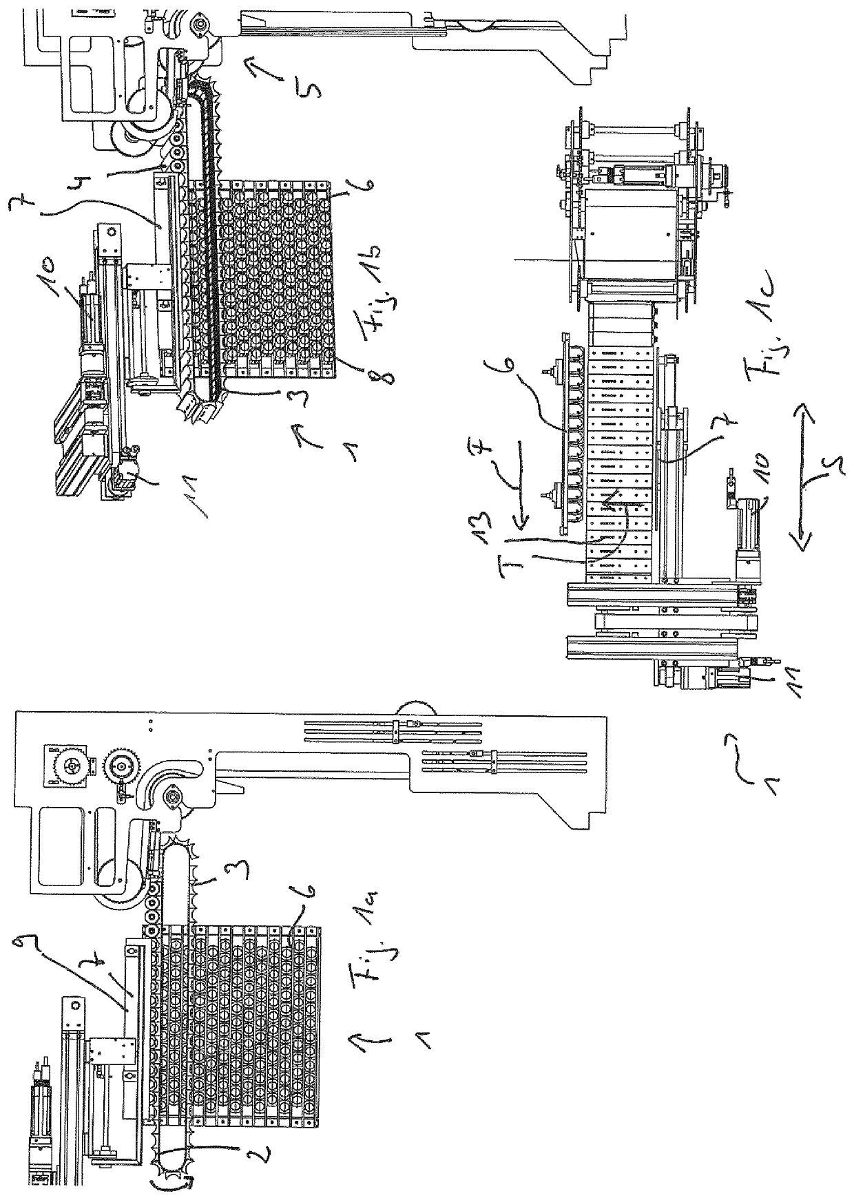
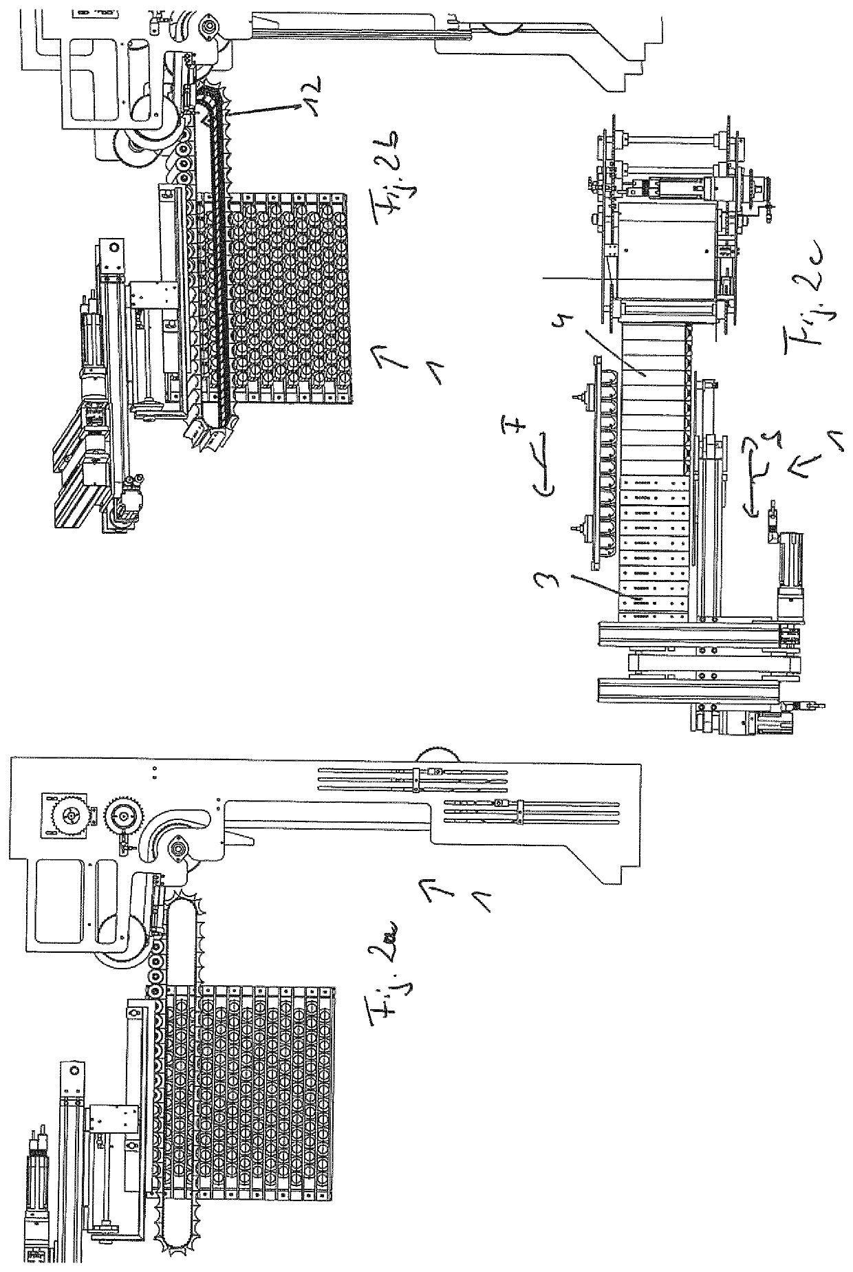
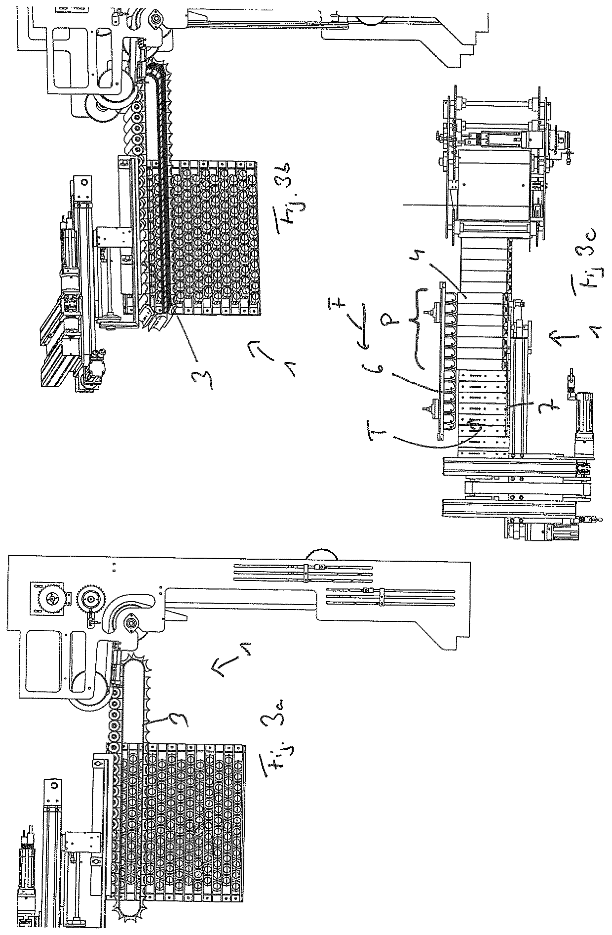
[0035]Hereinafter, first, the basic structure of a grouping device 1 configured according to the concept of the invention will be explained with reference to FIGS. 1a to 1c, and the explanations pertaining to FIGS. 2a to 8c will basically be restricted to changes in state in the course of the different operating states; the basic structure stays the same and all figures show the same device.

[0036]The grouping device 1 has a conveyor belt 3, which is realized as a pocket belt comprising a plurality of pockets 2 disposed one behind the other and each serving to receive a product in the shape of an empty can, an empty tube or an empty cartridge, said conveyor belt 3 being driven by drive means, in particular in the form of at least one servomotor, which are known per se and are not illustrated for the sake of clarity, a top (loading side) of the conveyor belt 3, shown in FIG. 1c, being driven along a straight conveying section S, which is preferably horizontal, for example, in a convey...


PUM


Abstract

The invention relates to a method for grouping preferably empty long products (4) embodied as tins, tubes or cartridges, the products (4) being delivered by a delivering conveyor device (5), preferably from a production line for producing the products (4), and placed on a conveyer belt (3) and transported thereby at a conveying speed along a conveying section (S) in a conveying direction (F), a product group (P) comprising a plurality of the products (4) being transferred by transfer means (7) at the same time from the conveyor belt (3) into receiving means (6), the transfer means (7) for transferring the products (4) being moved during the movement with the product group (P) in the conveying direction (F) at an angle, particularly perpendicularly, to the conveying direction (F) in a transfer direction (T) towards the receiving means (6), the receiving means (6) being moved perpendicularly to the conveying direction (F) and perpendicularly to the transfer direction (T), in order to be able to receive the subsequent product groups (P) above or below the already transferred product groups (P), after the transfer of each product group (P) or after the transfer of a plurality of product groups (P). The receiving means (6) and the transfer means (7) are moved along the conveying section (S) in the conveying direction (F) during the transfer of the product group (P), particularly synchronously with the conveyor belt (3) and the product groups (P) conveyed thereon and to be passed on, and following a successful transfer, are moved along the conveying section (S), in the opposite direction to the conveying direction (F), in order to transfer another product group (P′) into the receiving means (6).

Description

BACKGROUND OF THE INVENTION[0001]The invention relates to a method for grouping in particular empty oblong products in the form of cans, tubes or cartridges, the preferably cylindrical products being delivered by a delivering conveyor, preferably from a production line for producing the products, and placed on a conveyor belt (transport belt) and conveyed by it at a conveying speed along a conveying section in a conveying direction, a group of products comprising several of the products being simultaneously transferred from the conveyor belt into receiving means, such as a pin plate, or immediately into an outer packaging by transfer means, said transfer means being displaced toward the receiving means in a transfer direction at an angle, in particular perpendicular to the conveying direction so as to transfer the products while moving with the group of products in the conveying direction, and the receiving means being displaced perpendicular to the conveying direction and perpendic...

Claims


Application Information

Patent Timeline
Patent Type & Authority Patents(United States)
IPC IPC(8): B65B43/54B65G65/00B65B35/40B65B19/34
CPCB65B35/405B65B43/54B65G65/00B65B19/34B65G2201/0252
Inventor ALIG, LUKAS
Owner PACKSYS GLOBAL
Why Eureka
Try Eureka