Eureka AIR delivers breakthrough ideas for toughest innovation challenges, trusted by R&D personnel around the world.

Electrostatic discharge structure of liquid crystal display panel, liquid crystal display panel and liquid crystal display device

a liquid crystal display panel and electrostatic discharge technology, applied in non-linear optics, instruments, optics, etc., can solve the problems of poor display, increased process difficulty, and usually difficult dissipation, and achieve the effect of improving the anti-static ability of the liquid crystal display panel

Active Publication Date: 2020-04-07
WUHAN CHINA STAR OPTOELECTRONICS TECH CO LTD
View PDF2 Cites 3 Cited by
  • Summary
  • Abstract
  • Description
  • Claims
  • Application Information

AI Technical Summary

Benefits of technology

[0008]The technical problem to be solved by the present disclosure is to provide an electrostatic discharge structure of a liquid crystal display panel, a liquid crystal display panel and a liquid crystal display device, which can speed up the discharge of static electricity and greatly improve the static electricity generated by the tearing film and the coating film.
[0018]The implementation of the embodiments of the present disclosure has the following beneficial effects:
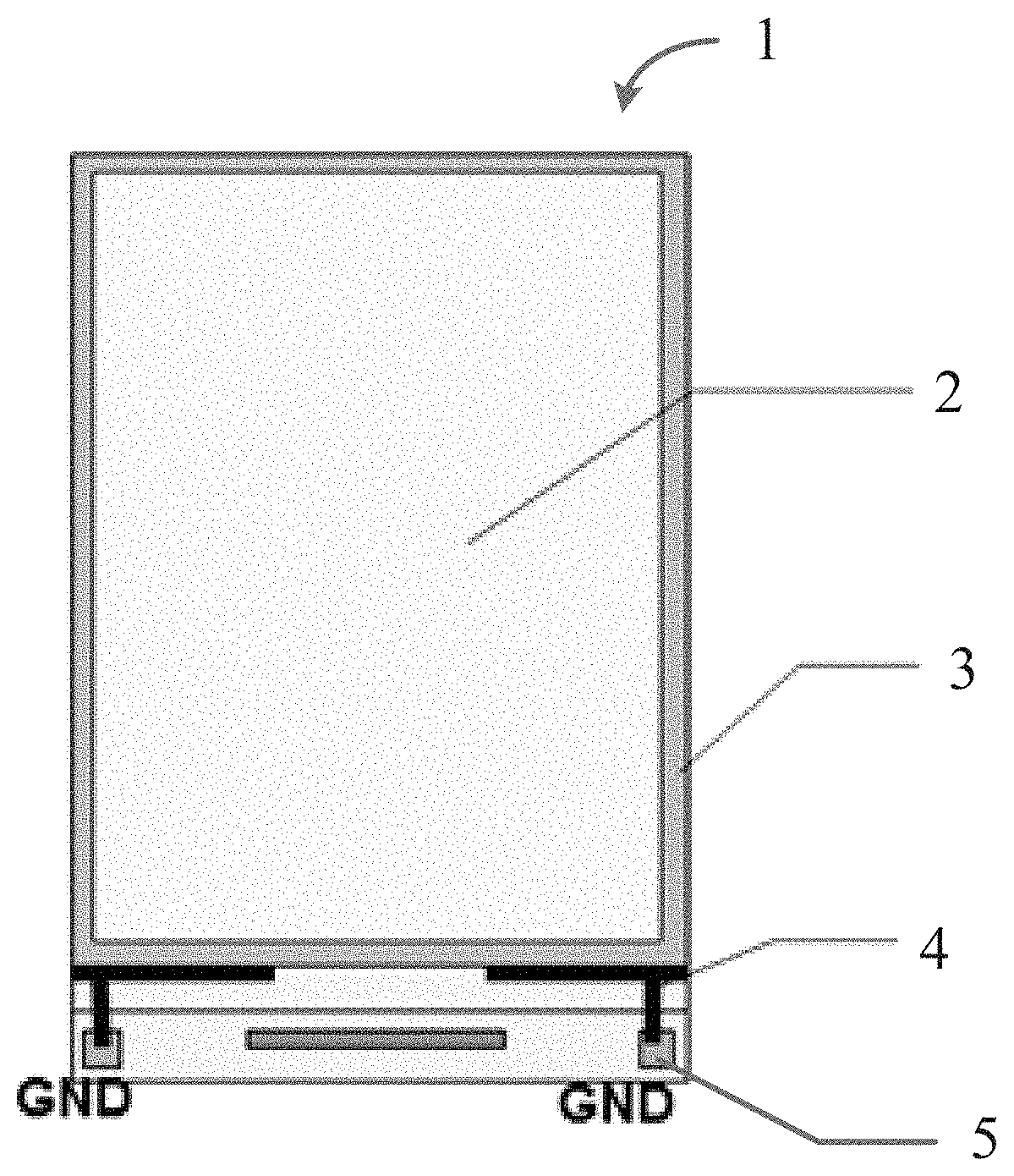
[0019]according to an embodiment of the present disclosure, by providing a conductive material layer around the high-resistance film of the cover glass panel and electrically connecting the conductive material to the GND pins of the TFT substrate, the contact area with the high-resistance film can be increased, electrostatic discharge can be accelerated, the static electricity generated by the tearing film and the film can be greatly improved, so as to improve the antistatic ability of the liquid crystal display panel;in addition, it is easy to measure the conductive status of the conductive silver paste, thus increasing the convenience of maintenance.

Problems solved by technology

In the prior art, the surface of an In-Plane Switching (IPS) display must have a grounded shield layer, otherwise the external electric field will affect the flip state of the liquid crystal molecules, resulting in poor display.
Since the high-resistance shield layer is much larger than the resistance of ITO, the static electricity generated during tearing / covering the protective film or the static electricity generated in the ESD test are hard to dissipate, resulting in the module emitting green, white, purple and other colors, and is usually difficult to dissipate in a long time (e.g., 10 s).
first, replacing the protective film suppliers, however, due to the surface resistance of the material of the protective film of the manufacturers used are not the same, resulting in the matched types are not the same;
second, increasing the area of the silver paste to speed up the discharge of the static electricity.
However, this will increase the difficulty of the process, increase the risk of excess paste, and increase the cost substantially.
Moreover, it is impossible to measure whether the silver paste is turned on with a multimeter.

Method used


Image

  • Electrostatic discharge structure of liquid crystal display panel, liquid crystal display panel and liquid crystal display device

Examples


Embodiment Construction

[0022]The technical solutions in the embodiments of the present disclosure will be described clearly and completely below with reference to the accompanying drawings in the embodiments of the present disclosure. Apparently, the described embodiments are merely some but not all embodiments of the present disclosure. All other embodiments obtained by a person of ordinary skill in the art based on the embodiments of the present disclosure without creative efforts shall fall within the protection scope of the present disclosure.

[0023]In addition, the following description of the embodiments is given with reference to the appended drawings, for the purpose of illustrating certain embodiments in which the disclosure may be practiced. As used herein, directional terms, such as “upper”, “lower”, “front”, “back”, “left”, “right”, “inside”, “outside”, “side” and the like, are only referring to the direction of the additional figures, thus, the directional terms used are used to better and mor...


PUM

PropertyMeasurementUnit
resistanceaaaaaaaaaa
square resistanceaaaaaaaaaa
conductiveaaaaaaaaaa

Abstract

The present disclosure discloses an electrostatic discharge structure of a LCD panel for mounting on a LCD panel with a high-resistance film, wherein the LCD panel includes a glass layer on an uppermost layer of the LCD panel covered with a high-resistance film, an edge reserved around the high-resistance film, and a conductive material layer arranged on the edge reserved on the glass panel, wherein the conductive material layer is in contact with a periphery of the high-resistance film, and the conductive material layer is connected to a GND pin of the TFT substrate through a conductive silver paste. The present disclosure also discloses a LCD panel and a LCD device. According to the embodiments of the present disclosure which can speed up the discharge of static electricity and greatly improve the static electricity generated by the tearing film and the coating film.

Description

RELATED APPLICATIONS[0001]The present application is a National Phase of International Application Number PCT / CN2017 / 116409, filed Dec. 15, 2017, and claims the priority of China Application CN 201710757954.0, filed Aug. 29, 2017.FIELD OF THE DISCLOSURE[0002]The present disclosure relates to a thin film transistor (TFT) technology, and more particularly to an electrostatic discharge structure of a liquid crystal display panel, a liquid crystal display panel and a liquid crystal display device.BACKGROUND OF THE DISCLOSURE[0003]In the prior art, the surface of an In-Plane Switching (IPS) display must have a grounded shield layer, otherwise the external electric field will affect the flip state of the liquid crystal molecules, resulting in poor display.[0004]In addition, in-cell display screen (a display panel that incorporates touch panel functionality into liquid crystal pixels) with a good grounding shield layer, will completely shield the touch signal in the cell, so that a high-re...

Claims


Application Information

Patent Timeline
Patent Type & Authority Patents(United States)
IPC IPC(8): G02F1/1333G02F1/1362
CPCG02F1/133308G02F1/136204G02F2001/133334G02F2001/133331G02F2202/22G02F1/133334G02F1/133331
Inventor LIN, DAN
Owner WUHAN CHINA STAR OPTOELECTRONICS TECH CO LTD
Why Eureka
Eureka Blog
Learn More