Fluidized bed device and method for coating particles or granulation

a fluidized bed and generator technology, applied in lighting and heating apparatus, granular material drying, furnaces, etc., can solve the problems of unchangeable ratio of tangential velocity and axial velocity, risk of coating film or granule damage, uneven wetting or agglomeration, etc., to facilitate the development of spray patterns, reduce the attrition of particles, and improve the effect of performan

Active Publication Date: 2020-04-21
TIANJIN CENAX BIOTECH CO LTD
View PDF17 Cites 0 Cited by
  • Summary
  • Abstract
  • Description
  • Claims
  • Application Information

AI Technical Summary

Benefits of technology

[0010]Accordingly, one conception of the present invention is an aerodynamic means of introducing a rotational rising air stream near the sprayer in the upward flow bed area in the partition to facilitate the development of the spray pattern and the particle flow pattern. Meanwhile the particles are subjected into a rotational rising path and are allowed to spin separately due to slight friction between the particles and the inner wall of the partition, thereby opportunities for the particles to obtain a more uniform spraying when subsequently passing through the spray zone above the nozzle are increased, so that the particles in the fluidized bed apparatus are ensured to be prevented from entering into the spray zone and contacting with the droplets here until the density of the droplets decreases due to the sufficient development of the spray pattern, wherein the attrition of the particles is minimized due to the spiral upward motion of the particles along the inner wall of the partition. Apart from the air vortex formed on the basis of generating in the vertical direction / guiding in the horizontal direction in the prior art, the swirling air stream is formed by generating in the horizontal direction / guiding in the vertical direction according to the conception of the present invention, such that the swirling air stream accelerates the particles continuously and steadily in the tangential direction in the preset vertical section of the partition, which contributes to the development of the spray pattern and the particle flow pattern, and optimizes the convection path of the product. Furthermore, a conventional fluidized bed apparatus can be simply retrofitted with the swirl generator according to the present invention as an accessory so as to improve its performance.
[0011]Another conception of the present invention is an aerodynamic means of utilizing dual partitions instead of single-partition and introducing a descending air stream in the descending flow bed area between the dual partitions, which allows the sprayed particles to be differentiated according to the particle sizes and distinctively treats the particles of different particle sizes respectively, thereby to prevent the small particles from mutual adhesions due to their high surface energy in the process of coating or granulating, wherein the small particles are selectively treated continuously and circularly to increase the particle size rapidly till all the particles present in a uniform particle size. Meanwhile the adverse effect of non-uniform spraying due to the mutual obscuring effect among the particles is eliminated or minimized. In such way, the adaptability of the fluidized bed apparatus according to the present invention is improved in the adaption capability to the process requirements of the particles with the high surface energy, and the application field of the process of coating or granulating is expanded.

Problems solved by technology

However, due to the high radial velocity vector of the diverting air stream in the process, the particles may collide with the inner wall of the partition, which can cause a risk of damage to the coating film or granules.
However, due to the high velocity vector in the axial direction the air vortex impedes the sufficient development of the spray pattern and the particle flow pattern before entering of the particles into the spray zone, which can cause a risk of over-wetting, uneven-wetting or agglomeration.
However, in one aspect, since the tangential velocity and axial velocity of the air vortex are not controllable separately, the ratio of the tangential velocity and axial velocity is unchangeable, so that the air vortex is not able to meet concrete requirements of the specific process varying in terms of batch size, particle size and process property, etc., which means the air vortex can't be optimized to suit a specific process.
In another aspect, the air vortex generated by the air vortex generator shaped as a circular plate is characterized with being stronger in the central area near the sprayer and being weaker in the surrounding area away from the sprayer, such that the air vortex impedes the development of the spray pattern and therefore interfere with the sufficient atomization of the droplets, which can cause a risk of over-wetting and uneven-wetting.
In a further aspect, due to the immediate expansion of the air vortex after passing through the generator and the sudden acceleration of the particles on the generator, the air vortex impedes the development of the particle flow pattern and therefore interfere with the motion of the particles, which means the particles are subjected to an undesired irregular movement in the process.

Method used


Image

  • Fluidized bed device and method for coating particles or granulation
  • Fluidized bed device and method for coating particles or granulation
  • Fluidized bed device and method for coating particles or granulation

Examples


first embodiment

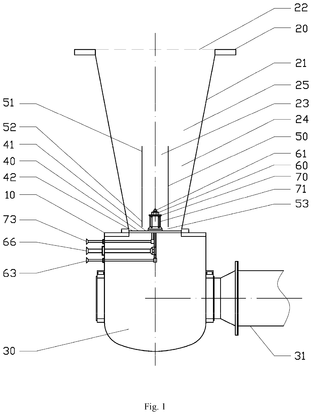
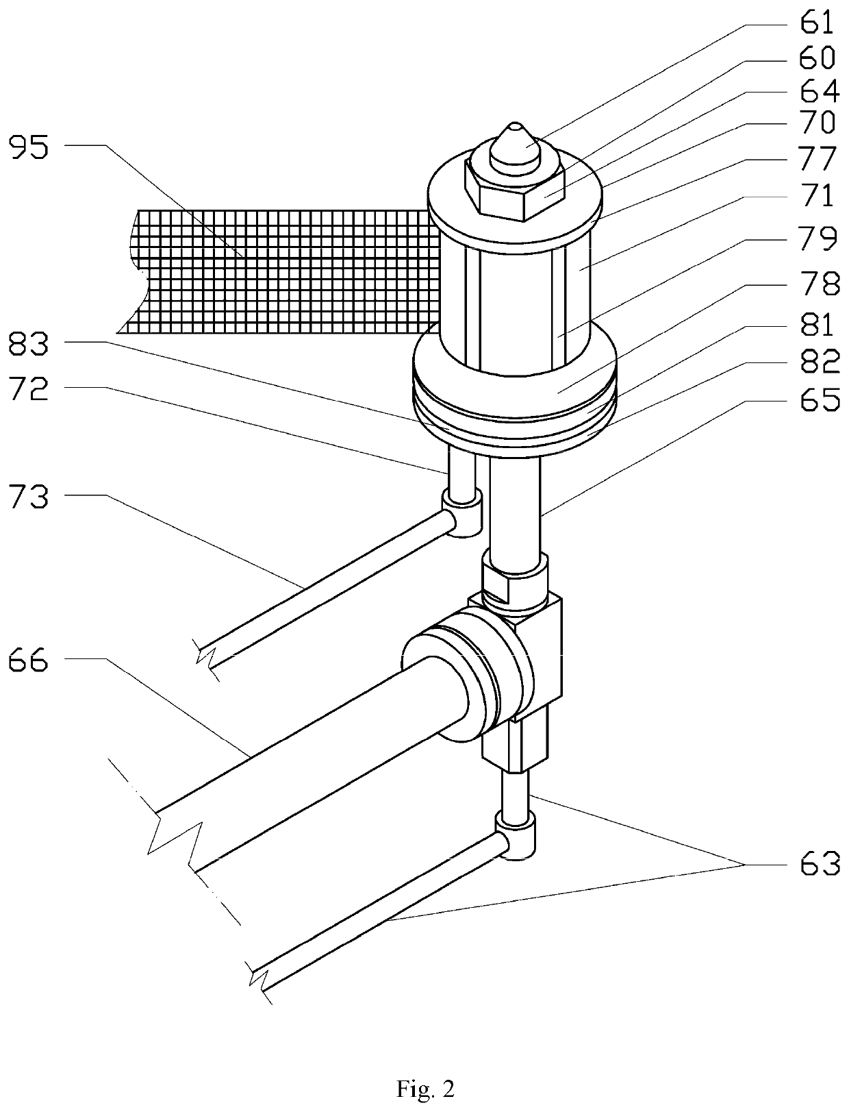
[0069]According to the first embodiment of the present invention, a swirl generator 70 is further provided, which can be combined with the sprayer 60 of the above-mentioned conventional fluidized bed apparatus to provide a swirling air stream in the circumferentially outwardly direction relative to the sprayer 60. More particularly, the swirl generator 70 includes a sleeve 71, which can be assembled on the sprayer body 62 and comprises an upper end 77 and a lower end 78, wherein guiding slots 79 extend axially therebetween. And the swirl generator 70 further includes a manifold 81 and a collar 82, which are fixed on the lower end 78, wherein an air pipeline 73 extending from the source of compressed air is connected to the manifold 81 and the collar 82 via a fitting 72. The bottom of the manifold 81 includes a projection 83 adapted to be embedded in a central opening of the air distribution plate 40, wherein the air distribution plate 40 is sandwiched between the manifold 81 and col...

second embodiment

[0074]With reference to FIG. 8, the second embodiment of the present invention is an improved solution based on the first embodiment of the present invention, wherein a secondary partition 54 is provided besides the partition 50 so as to provide a downward descending air stream between the partition 50 and the secondary partition 54. The usually cylindrical-shaped secondary partition 54 is larger in diameter than the partition 50 and is positioned coaxially with the partition 50 so as to form an annular air passage 26 between the partition 50 and the secondary partition 54. The cylindrical partition 50, for example in form of cylinder, and secondary partition 54 are mounted in the center of the container 20 and together separate the container 20 into a central upward flow bed area 23, a surrounding downward flow bed area 24 and a descending flow bed area 27 sandwiched between the partition 50 and the secondary partition 54. The secondary partition 54 comprises an open upper end 55 a...


PUM

PropertyMeasurementUnit
elevation angleaaaaaaaaaa
diameteraaaaaaaaaa

Abstract

The present invention relates to a fluidized bed apparatus and a method for particle-coating or granulating, the fluidized bed apparatus includes a swirl generator which is mounted on a sprayer body in the fluidized bed apparatus and extends throughout an air distribution plate and is connected to a source of compressed air. The swirl generator comprises a tubular sleeve extending circumferentially around the sprayer body, and an air chamber is defined between the sleeve and the sprayer body, wherein the sleeve comprises a plurality of guiding slots. The air from the source of compressed air via the air chamber is directed by said guiding slots to rotate outwardly, so as to provide a swirling air stream circumferentially outwardly relative to the sprayer. The present invention can facilitate the development of the spray pattern and the particle flow pattern and allows the particles to spin respectively due to slight friction with the inner wall of the partition, thereby opportunities for the particles to obtain a more uniform spray when subsequently passing through the spray zone above the nozzle are increased, so that performance of the fluidized bed apparatus is improved.

Description

CROSS REFERENCE TO RELATED APPLICATIONS[0001]This application is a 35 U.S.C. § 371 national stage filing of International Application No. PCT / CN2016 / 073224, filed on Feb. 2, 2016, the disclosure of which is incorporated herein by reference.FIELD OF THE INVENTION[0002]The present invention relates to a swirl generator of a fluidized bed apparatus for particle-coating or granulating, a fluidized bed apparatus comprising the swirl generator and a method for coating particles or granulating used in the fluidized bed apparatus. The present invention further relates to dual partitions, instead of a single partition, used in a fluidized bed apparatus for particle-coating or granulating. In addition, the present invention relates to a fluidized bed apparatus comprising the dual partitions combining with a swirl generator and a method of particle-coating or granulating used in the fluidized bed apparatus.BACKGROUND OF THE INVENTION[0003]Various specialized equipment and apparatuses have been...

Claims


Application Information

Patent Timeline
Patent Type & Authority Patents(United States)
IPC IPC(8): B01J2/16B05D1/02B01J2/00B01J8/24B05B1/34B01F13/02F26B3/092B01F33/40
CPCB01J2/16B01J2/006F26B3/0926F26B2200/08B05B1/34B01F13/0261B01J8/24B01F33/4061
Inventor LIU, YIMINGLU, HUIFENLIU, FEILIU, YITAOCHEN, MIN
Owner TIANJIN CENAX BIOTECH CO LTD
Why Eureka
Try Eureka