Arrangement for cooling a closed cabinet

a technology for sealing cabinets and closed cabinets, which is applied in the direction of domestic cooling devices, indirect heat exchangers, lighting and heating devices, etc., can solve the problems of difficult to utilize economical and long-life cooling solutions for closed cabinet cooling, and the risk of cooling fluid leakage, so as to achieve better optimization and cost-effective

Active Publication Date: 2020-04-28
ABB (SCHWEIZ) AG
View PDF21 Cites 1 Cited by
  • Summary
  • Abstract
  • Description
  • Claims
  • Application Information

AI Technical Summary

Benefits of technology

[0005]The invention is extremely useful in cases where two different IP spaces must be solid / homogenous without any went-throughs. A practical example is EX Cabinet (Explosion Proof Cabinet) where the inner and outer spaces must be kept separated. The invention helps in cooling of the interior of the EX Cabinet and transfers the heat energy to a contact surface of the cabinet which then can be cooled further by e.g. liquid cooling. This way there is no went-throughs through the cabinet wall, but the interior of the cabinet is cooled very effectively. This also enables very easy installation and maintenance of the arrangement of the invention.
[0007]For using two-phase cooling for heat exchange there are several advantages compared to conventional solutions. This system can be better optimized and is more cost efficient. For heat exchange point of view, typically restricted area is air-side heat transfer rate and by using two-phase principle, heat exchange in air-side is possible to increase almost without any area limit to get air-side cooling working optimally, because evaporation is happening in constant temperature.

Problems solved by technology

Now different heat exchangers, utilizing customer cooling fluids, are used for closed cabinet cooling, but there is always a risk of leakage of the cooling fluid.
Also different cooling fluids and pressure levels make it difficult to utilize economical and long life cooling solutions for closed cabinet cooling.

Method used


Image

  • Arrangement for cooling a closed cabinet
  • Arrangement for cooling a closed cabinet
  • Arrangement for cooling a closed cabinet

Examples


Embodiment Construction

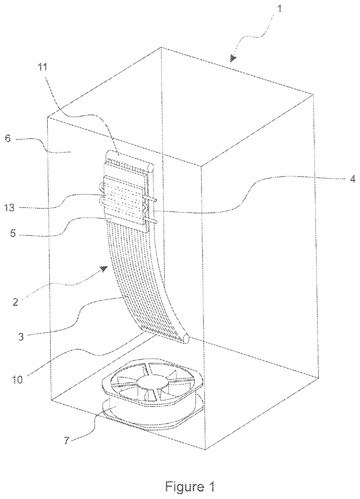
[0016]The arrangement according to FIG. 1 shows a closed, sealed IP cabinet 1, the inside of which must be cooled. For that purpose a thermosiphon heat exchanger 2 is disposed inside the cabinet 1.

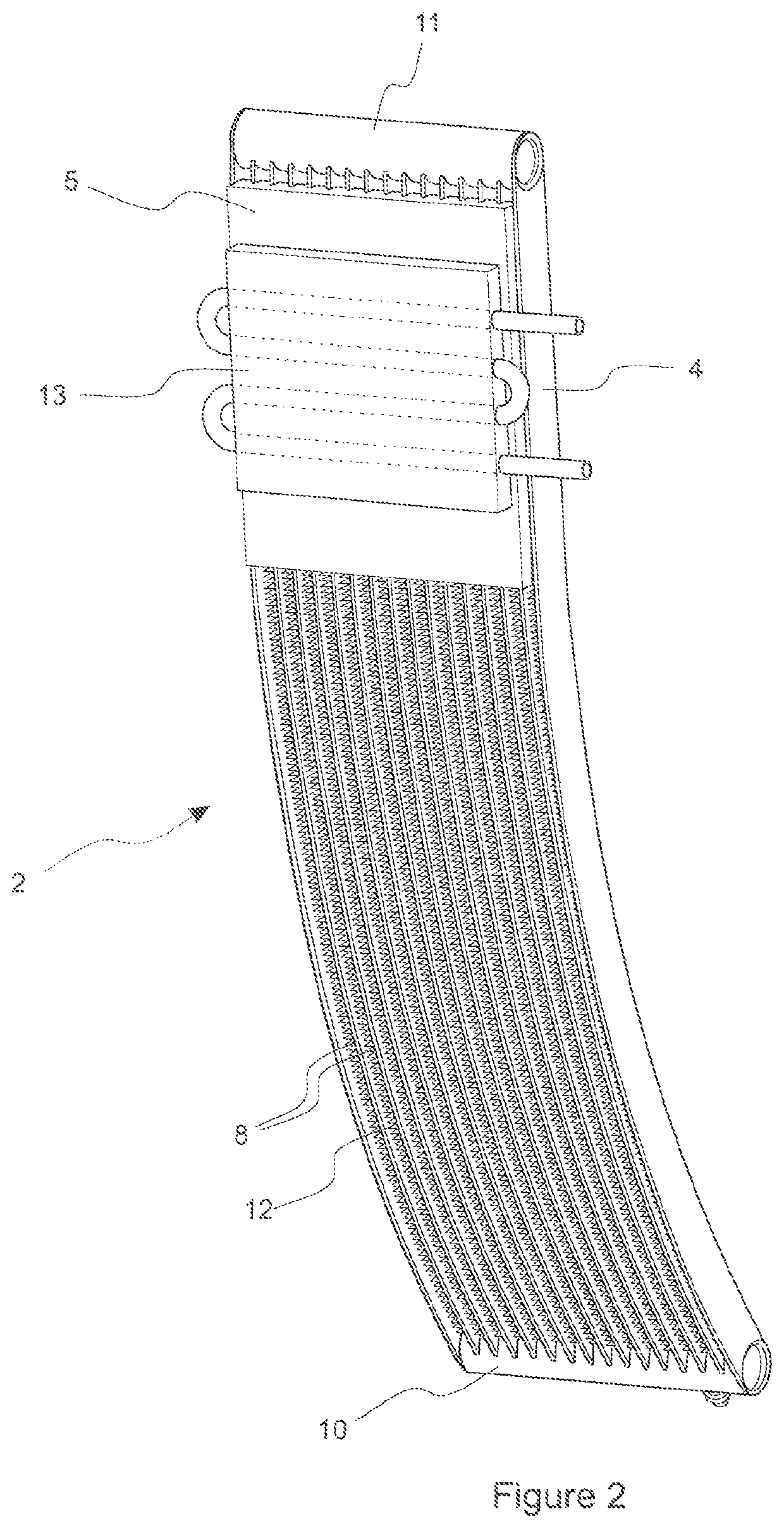
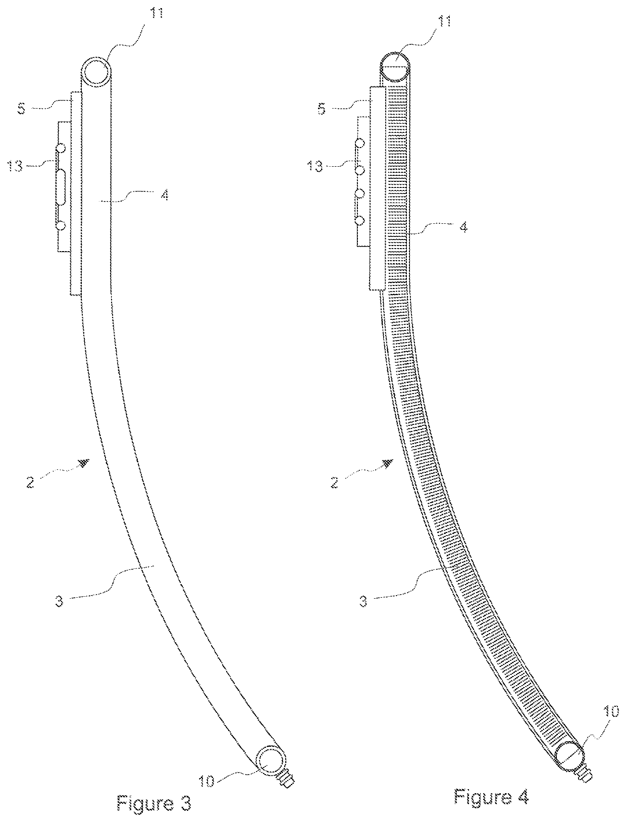
[0017]The heat exchanger 2 according to FIGS. 1 to 4 comprises an evaporator 3 (an evaporator end) and a condenser 4 (a condenser end) for circulating a working fluid between the evaporator 3 and the condenser 4 in a closed loop, wherein the working fluid evaporated in the evaporator 3 by heat flows to the condenser 4 for cooling and the condensed working fluid flows back to the evaporator 3.

[0018]The evaporator 3 is exposed to hot air flow generated inside the cabinet 1, and a heat transfer element 5 is attached to the condenser 4 in a sealed manner through a cabinet wall 6 for transferring heat to the outside of the cabinet 1.

[0019]The heat exchanger 2 of this example is based on gravity heat pipe principle, wherein the condenser 4 is above the evaporator 3. Further, the heat exchanger 2...


PUM


Abstract

An arrangement for cooling a closed, sealed cabinet (1), comprising a thermosiphon heat exchanger (2) disposed inside the cabinet (1) and having an evaporator (3) and a condenser (4) for circulating a working fluid between the evaporator (3) and the condenser (4) in a closed loop, wherein the working fluid evaporated in the evaporator (3) by heat flows to the condenser (4) for cooling and the condensed working fluid flows back to the evaporator (3). The evaporator (3) is exposed to hot air flow generated inside the cabinet (1), and a heat transfer element (5) is attached to the condenser (3) in a sealed manner through a cabinet wall (6) for transferring heat to the outside of the cabinet (1).

Description

FIELD OF THE INVENTION[0001]The invention relates to an arrangement for cooling a closed, sealed cabinet, comprising a thermosiphon heat exchanger disposed inside the cabinet and having an evaporator and a condenser for circulating a working fluid between the evaporator and the condenser in a closed loop, wherein the working fluid evaporated in the evaporator by heat flows to the condenser for cooling and the condensed working fluid flows back to the evaporator.DESCRIPTION OF PRIOR ART[0002]Now different heat exchangers, utilizing customer cooling fluids, are used for closed cabinet cooling, but there is always a risk of leakage of the cooling fluid. Also different cooling fluids and pressure levels make it difficult to utilize economical and long life cooling solutions for closed cabinet cooling.SUMMARY OF THE INVENTION[0003]An object of the present invention is to provide an arrangement to solve the above problems. The objects of the invention are achieved by an arrangement which ...

Claims


Application Information

Patent Timeline
Patent Type & Authority Patents(United States)
IPC IPC(8): F28D15/02F25D3/06F28F1/02F28F1/32F28F9/02
CPCF28F9/0243F28F1/32F28D15/0275F25D3/06F28F1/022F28D15/025F28D2015/0216H05K7/20336H05K7/20936F28D1/0471F28D15/0233F28D15/0266F28D2001/0273H05K7/20609H05K7/20681
Inventor LAURILA, RISTOVIITANEN, TEROAGOSTINI, BRUNO
Owner ABB (SCHWEIZ) AG
Why Eureka
Try Eureka