
Turbine blade with tip overhang along suction side

a turbine blade and suction side technology, applied in the direction of blade accessories, machine/engine, leakage prevention, etc., can solve the problems of significant heat transfer, large overhang length, and large aerodynamic loss, and achieve the effect of reducing the overhang length

Active Publication Date: 2020-05-05
ROLLS ROYCE PLC +1
View PDF41 Cites 2 Cited by
  • Summary
  • Abstract
  • Description
  • Claims
  • Application Information

AI Technical Summary

Benefits of technology

The patent describes how a part of a structure may gradually decrease in size as it moves towards the front and back ends. This change is called an overhang. The text suggests that the length of the overhang may gradually decrease towards the leading edge and the trailing edge of the structure. This information may be useful for designing and manufacturing various products.

Problems solved by technology

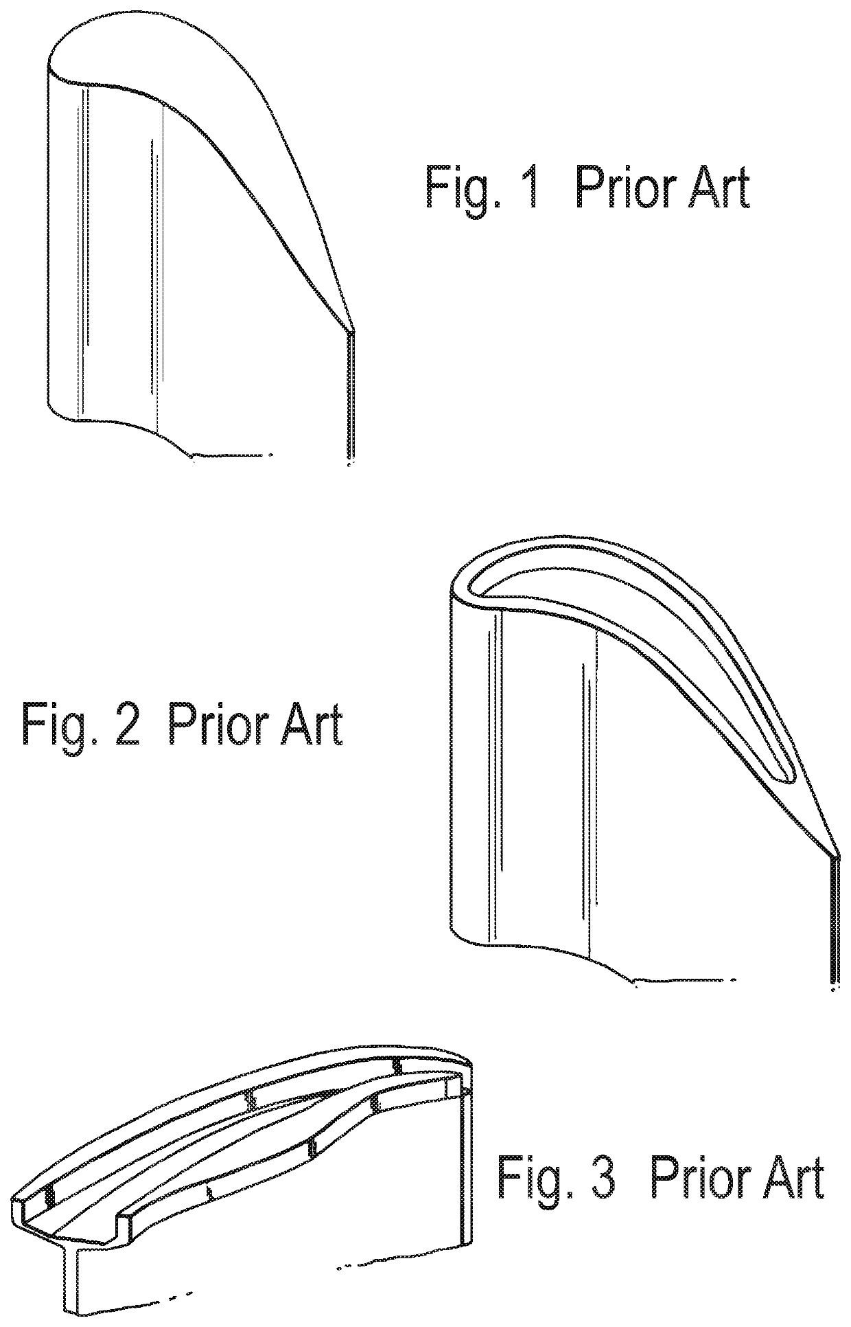
A flat tip design is typically associated with a relatively high aerodynamic loss due to the over-tip leakage flow and high heat transfer, although it is relatively simple to manufacture.
Whereas these blade designs help to prevent over-tip leakage, they both require substantial amounts of cooling air.
In particular, the over-tip leakage forms a vortex which impinges on the suction side of the blade causing significant heat transfer.

Method used


Image

  • Turbine blade with tip overhang along suction side
  • Turbine blade with tip overhang along suction side
  • Turbine blade with tip overhang along suction side

Examples


Embodiment Construction

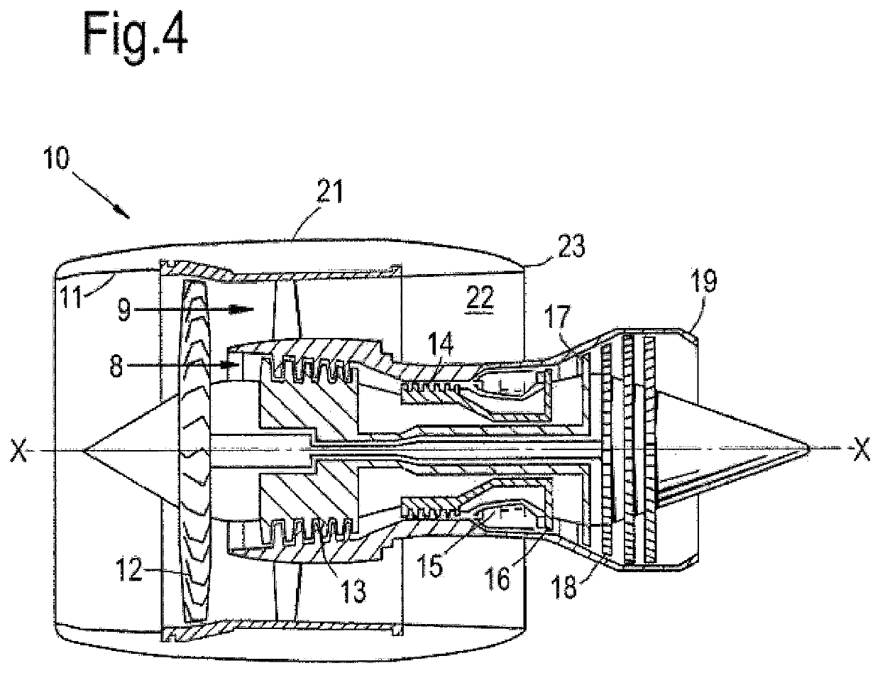
[0027]With reference to FIG. 4, a ducted fan gas turbine engine generally indicated at 10 has a principal and rotational axis X-X. The engine comprises, in axial flow series, an air intake 11, a propulsive fan 12, an intermediate pressure compressor 13, a high-pressure compressor 14, combustion equipment 15, a high-pressure turbine 16, and intermediate pressure turbine 17, a low-pressure turbine 18 and a core engine exhaust nozzle 19. A nacelle 21 generally surrounds the engine 10 and defines the intake 11, a bypass duct 22 and a bypass exhaust nozzle 23.

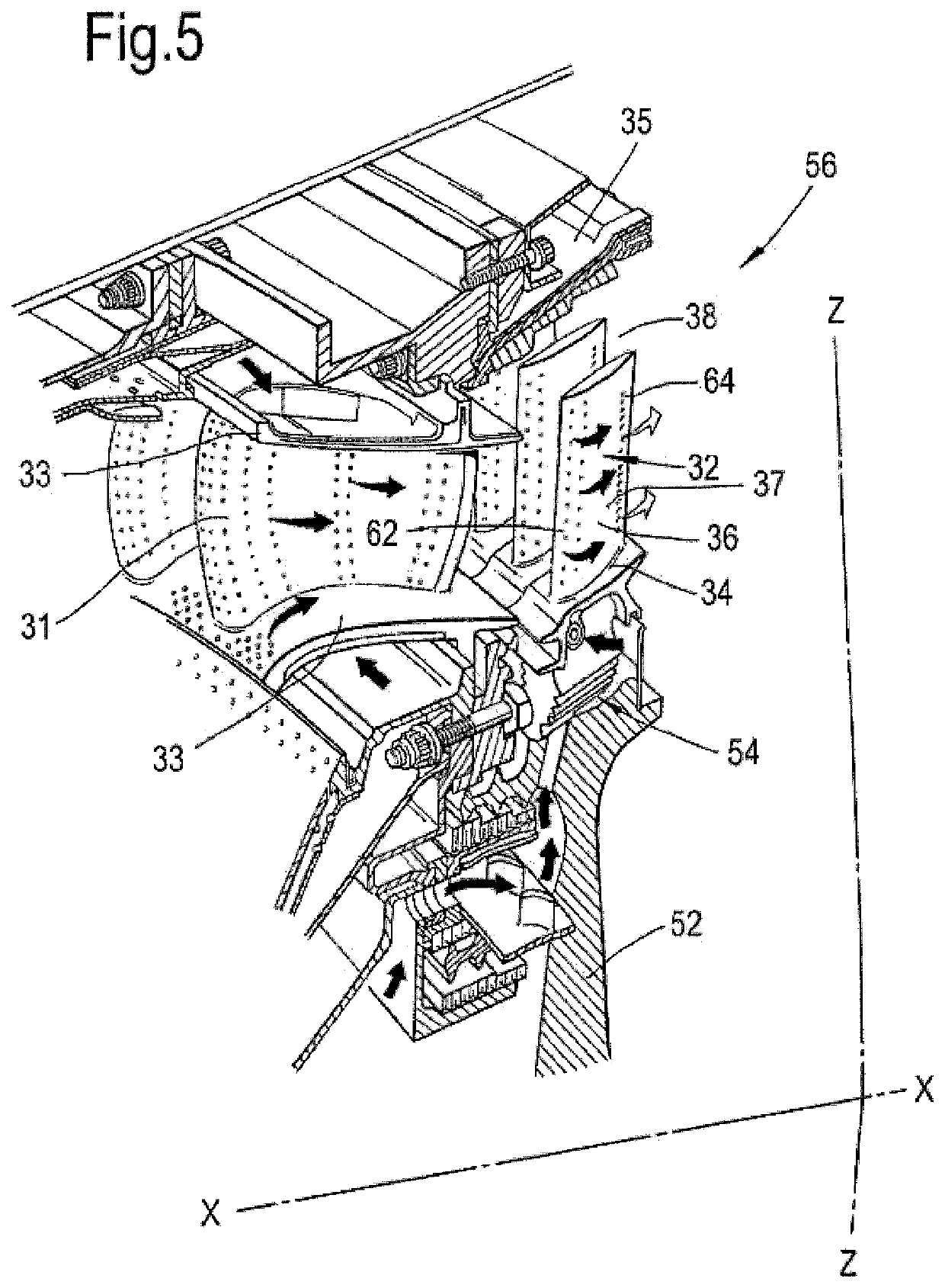
[0028]The gas turbine engine 10 works in a conventional manner so that air entering the intake 11 is accelerated by the fan 12 to produce two air flows: a first air flow 8 into the intermediate pressure compressor 13 and a second air flow 9 which passes through the bypass duct 22 to provide propulsive thrust. The intermediate pressure compressor 13 compresses the air flow 8 directed into it before delivering that air to the high pre...


PUM


Abstract

A turbine blade has a root portion, a platform and an aerofoil, the aerofoil is mounted on the platform and is formed by a pressure side wall and a suction side wall and has an outer surface, the pressure side wall and the suction side wall meet at a leading edge and a trailing edge, the aerofoil has an axial chord length, the suction side wall defines part of the radially outward surface of the aerofoil, the suction side wall defines an overhang, the overhang has a maximum overhang length that is between 5% and 20% of the axial chord length of the blade and is located between 5% and 50% of the suction surface length from the leading edge.

Description

FIELD OF THE INVENTION[0001]The present invention relates to a blade of a turbine and preferably for a gas turbine engine, and in particular a structure of the tip of the blade.BACKGROUND OF THE INVENTION[0002]For turbine rotor blades and particularly high pressure (HP) turbine blades, there is an industry wide and ever-important objective to minimise both over-tip leakage (OTL) of hot working gases between a tip of the blades and a casing and heat transfer from the hot working gases to the blade. OTL occurs because of the pressure differential between a pressure-side and a suction-side of a turbine blade; this pressure differential can be referred to as ‘driving pressure’.[0003]In general, there are three types of tip geometry configurations which attempt to minimise over tip leakage: un-shrouded, partially shrouded (or ‘winglet’) and fully shrouded. The simplest form of tip geometry is an un-shrouded type having a flat tip (see FIG. 1). A flat tip design is typically associated wi...

Claims


Application Information

Patent Timeline
Patent Type & Authority Patents(United States)
IPC IPC(8): F01D5/20F01D5/14F01D11/08
CPCF01D5/20F01D5/141F01D11/08F05D2240/307
Inventor COULL, JOHN DAVIDATKINS, NICHOLAS ROBERTHODSON, HOWARD PETERWHITE, ADRIAN JAMESLEHMANN, KNUTHERM, MANUEL
Owner ROLLS ROYCE PLC
Learn More