Blade set manufacturing method, blade set and hair cutting appliance

a blade set and manufacturing method technology, applied in the direction of metal working devices, etc., can solve the problems of affecting the operation of the attachment comb, affecting the operation of the comb, so as to improve the operation performance, improve the operation efficiency, and expand the field of application.

Active Publication Date: 2020-06-02
KONINKLJIJKE PHILIPS NV
View PDF29 Cites 5 Cited by
  • Summary
  • Abstract
  • Description
  • Claims
  • Application Information

AI Technical Summary

Benefits of technology

[0015]It is an object of the present disclosure to provide a method of forming a stationary blade for a hair cutting appliance that tackles at least some of the above discussed issues and that preferably allows for adjustable blade sets that enable significantly enlarged length adjustment ranges which preferably results in an improved operational performance and an enlarged field of application of a respectively equipped hair cutting appliance.
[0016]Further, it is desirable to present a stationary blade manufacturing method which enables a further reduction of the number of accessory parts of a hair cutting appliance.
[0023]This aspect is based on the insight that the freedom of design for the stationary blade may be significantly improved by arranging the stationary blade as an assembled blade. When manufacturing conventional blade sets, flat metal material or metal blanks is / are used the height of which defines the overall height of the blade. Hence, the height of an involved pre-product component delimits the height on the stationary blade and, as a result, an achievable length adjustment range. As a result, a respectively equipped hair cutting appliance does not necessarily require an attachment comb to provide the desired length setting range. Operating the hair cutting appliance is facilitated when no additional comb has to be attached.
[0026]In other words, the orientation of any involved flat material may be rotated by 90° (degrees) when each tooth is made from a respective layer. Hence, a height to length ratio of the teeth may be significantly increased which enables a considerable tapering.
[0031]However, the step of providing the blade base may also involve providing a metal blade base which may be referred to, in some embodiments, as blade frame. Hence, the blade base is formed in a preceding step. An already formed blade base may be adequately suited for receiving and supporting the teeth of the stationary blade. However, given the general arrangement of the stationary blade in accordance with the above aspect, the blade base does not have to be made from a material that is suitable for forming cutting teeth comprising cutting edges. In other words, the tooth components that form the teeth may be grinded, hardened and / or comprise a surface treatment so as to improve the cutting performance of the blade set. The blade base basically does not need a respective processing or treatment. Hence, the blade base may be made from a lower-quality material than the tooth components.
[0045]As the thickness of sheet metal material is generally accurately determined within a narrow tolerance range, also the resulting stack may comprise a sufficiently precise width. When the tooth components are obtained from sheet metal material, a large degree of design freedom is provided. For instance, the tooth components may be significantly tapered which results in a considerably large cutting length adjustment range. Further, mounting features may be processed when the tooth components are separated from the sheet metal material. Generally, the tooth components may be formed with high repeatability which results in even and accurately formed teeth.

Problems solved by technology

As attachment combs are typically detachable, there is a certain losing risk.
Further, even though attachment combs are relatively simple parts, there are certain manufacturing costs, assembly costs and logistic expenses as additional separate parts are involved.
Further, operating the attachment combs is sometimes experienced as being uncomfortable, cumbersome, and somewhat outmoded.

Method used


Image

  • Blade set manufacturing method, blade set and hair cutting appliance
  • Blade set manufacturing method, blade set and hair cutting appliance
  • Blade set manufacturing method, blade set and hair cutting appliance

Examples


Embodiment Construction

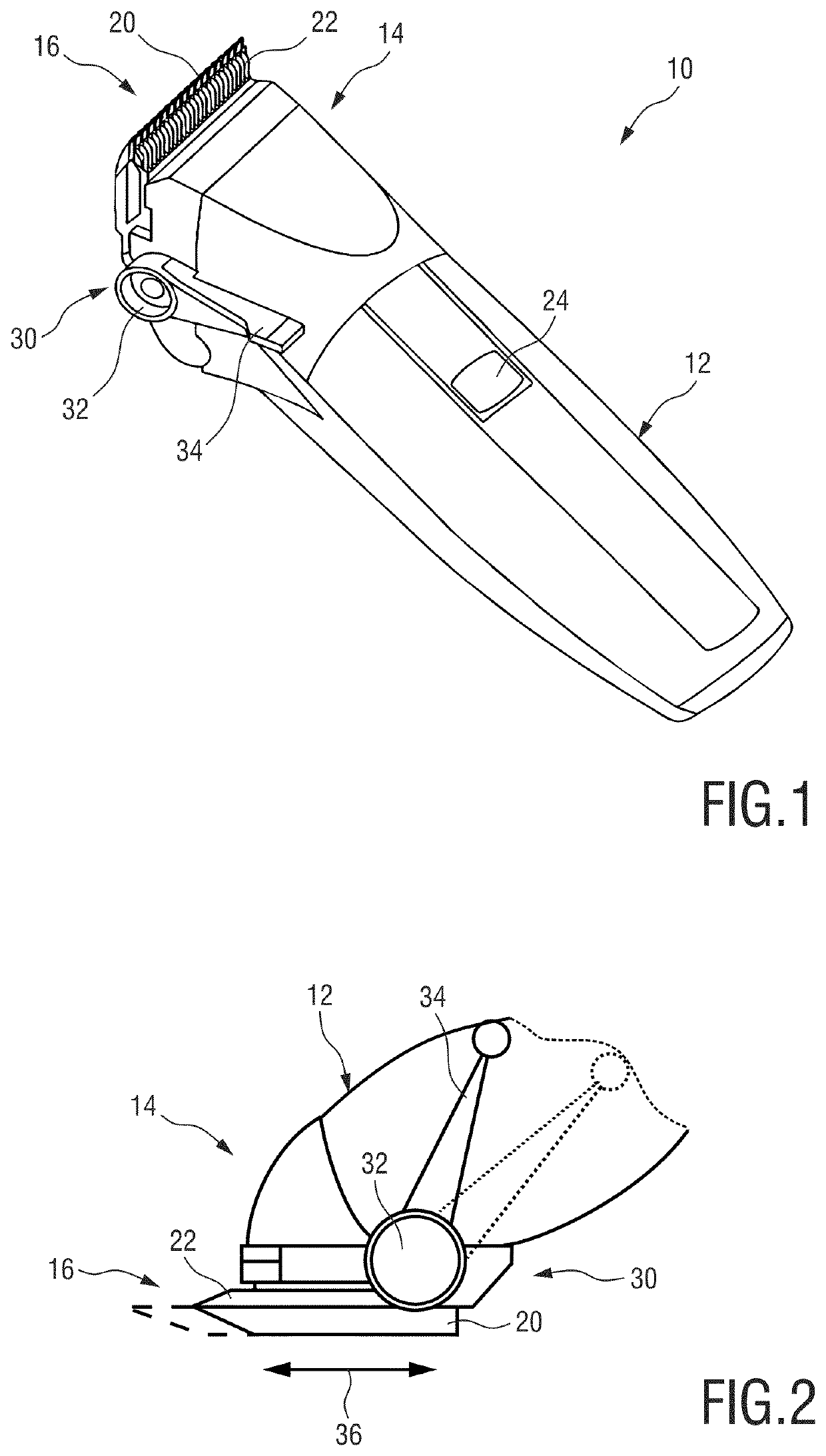
[0099]FIG. 1 shows a schematic perspective rear view of a hair cutting appliance 10, particularly an electrically operated hair cutting appliance 10. The appliance 10 may also be referred to as hair clipper or hair trimmer. The appliance 10 comprises a housing or housing portion 12 having a generally elongated shape. At a first, top end thereof, a cutting head 14 is provided. The cutting head 14 comprises a blade set assembly 16. The blade set assembly 16 comprises a stationary blade 20 and a movable cutter blade 22 that may be moved with respect to each other to cut hair. At a central portion and a second, bottom end of the housing 12, a handle or grip portion is formed. A user may grasp or grab the housing 12 at the grip portion.

[0100]The appliance 10 in accordance with the exemplary embodiment of FIG. 1 further comprises operator controls. For instance, an on-off switch or button 24 may be provided.

[0101]For illustrative purposes, the housing 12 of the hair cutting appliance 10 c...


PUM


Abstract

A stationary blade for a hair cutting appliance and a method of forming the stationary blade includes providing tooth components obtained from metal material, where the tooth components are arranged in a substantially flat fashion and are at least partially tapered towards a tip end. The method further includes arranging the tooth components next to each other to form a series of spaced apart teeth, where neighboring tooth components are arranged at a distance from one another; providing a blade base acting as a support receptacle, arranged to receive the tooth components; and interconnecting the tooth components and the blade base in a direct or mediate fashion, thereby forming teeth of the stationary blade.

Description

[0001]This application is the U.S. National Phase application under 35 U.S.C. § 371 of International Application No. PCT / EP2017 / 058155, filed on Apr. 5, 2017, which claims the benefit of European Application No. EPO 16163981.0 filed on Apr. 6, 2016. These applications are hereby incorporated by reference herein.FIELD OF THE INVENTION[0002]The present disclosure relates to a method of forming a stationary blade for a blade set of a hair cutting appliance, to a stationary blade, and to a hair cutting appliance implementing a blade set involving such a stationary blade.[0003]More particularly, the present disclosure relates to improvements in hair cutting devices wherein the cutting action is effectuated by reciprocating blades, such as clippers and trimmers. More specifically, the present disclosure relates to novel approaches to the design and production of stationary blades for blade sets that provide a considerably large length adjustment range. Hence, in at least some embodiments,...

Claims


Application Information

Patent Timeline
Patent Type & Authority Patents(United States)
IPC IPC(8): B26B19/38B26B19/04
CPCB26B19/3846B26B19/3893B26B19/048B26B19/38
Inventor SABLATSCHAN, SIEGFRIED
Owner KONINKLJIJKE PHILIPS NV
Why Eureka
Try Eureka