Gear box, driving device, and electronic apparatus

a driving device and electronic equipment technology, applied in the direction of gearing details, mechanical equipment, gearing, etc., can solve the problems of pinion gear idle with respect to the output shaft, damage to the casing, and high torque of the geared motor, so as to drive the output device smoothly over a long period of time

Active Publication Date: 2020-06-02
SEIKO INSTR INC
View PDF5 Cites 0 Cited by
  • Summary
  • Abstract
  • Description
  • Claims
  • Application Information

AI Technical Summary

Benefits of technology

[0013]According to this aspect, in a case where the shaft supporting wall is deflected and deformed to the second side in the axial direction due to an unintended external force when the output member is fixed to the rotation shaft, the supporting shaft abuts against the division wall in the axial direction. Accordingly, by restricting the displacement of the supporting shaft in the axial direction to the second side with respect to the casing, the deflecting deformation of the shaft supporting wall can be restricted. Therefore, even in a case where an unintentional load is applied to the rotation shaft when the output member is fixed to the rotation shaft, it is possible to suppress the lead to damage of the casing or the like.
[0032]According to this aspect, since the driving device of the aspect is provided, even in a case where the size and weight of the output device mounted on the driving device increases, it is possible to drive the output device smoothly over a long period of time.

Problems solved by technology

Therefore, high torque of the geared motor is required.
Therefore, in a case where the press-fitting load acting between the output shaft and the pinion gear is insufficient, there is a possibility that the pinion gear idles with respect to the output shaft.
On the other hand, if the press-fitting force at the time of press-fitting the pinion gear is increased so as to secure the press-fitting load, the portion of the casing that supports the output shaft may be deflected, possibly leading to damage of the casing or the like.
Particularly, in a case where the pinion gear is attached at the delivery destination, it is difficult to manage the type of the pinion gear, the press-fitting force, and the like, and the problems described above are likely to occur.
An unintended load when the pinion gear is fixed to the output shaft may cause the portion of the casing that supports the output shaft to deflect and possibly lead to damage to the casing or the like.
Accordingly, the casing is damaged by the load applied to the pinion gear and the output shaft, or the pinion gear is attached to the output shaft in a state where the casing is deflected.
As a result, there is a case that the gear box does not operate normally.

Method used


Image

  • Gear box, driving device, and electronic apparatus
  • Gear box, driving device, and electronic apparatus
  • Gear box, driving device, and electronic apparatus

Examples


Embodiment Construction

[0041]Hereinafter, embodiments of a gear box and a driving device according to the invention will be described with reference to the drawings.

[Imaging Device]

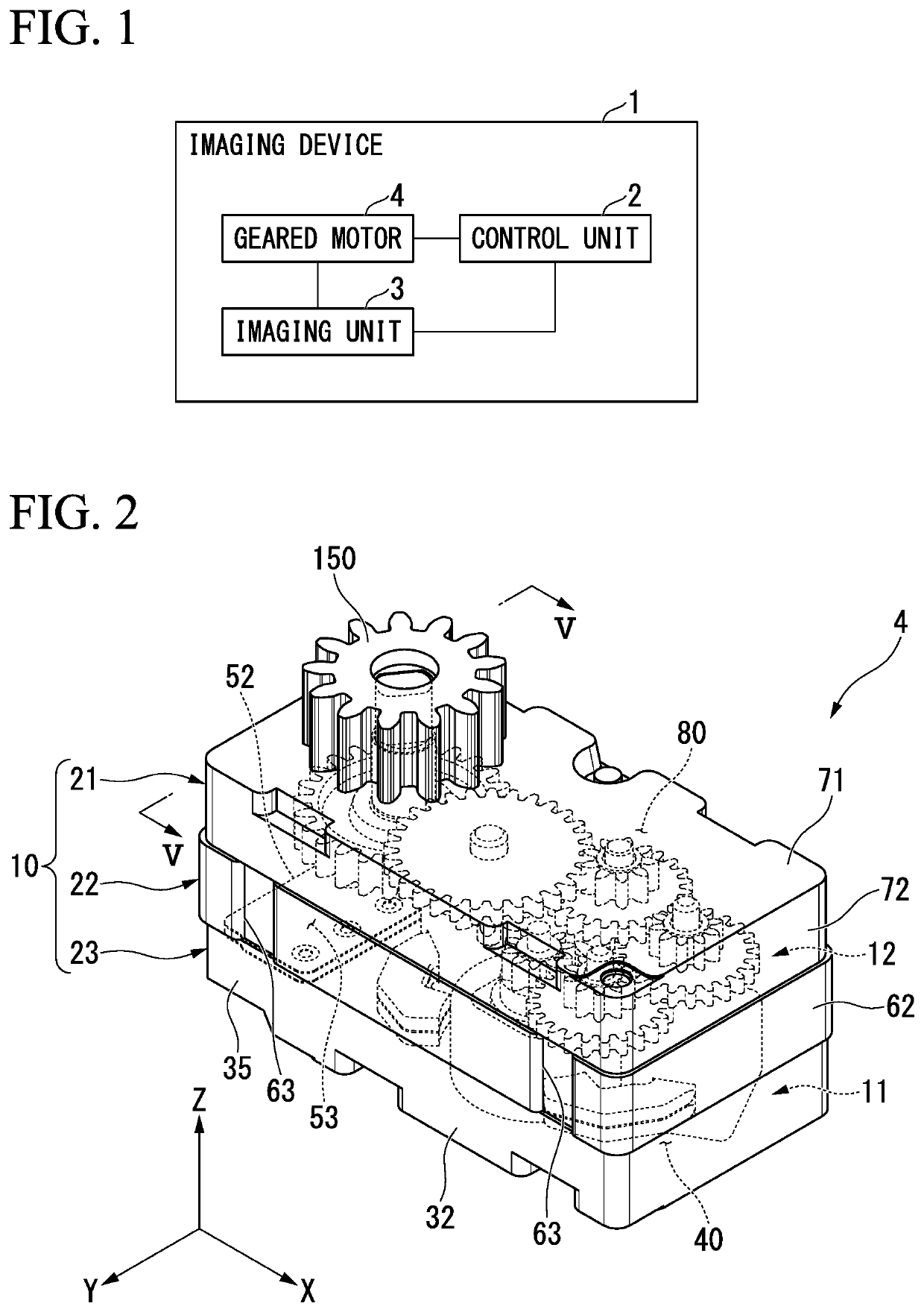
[0042]FIG. 1 is a block diagram showing an imaging device 1.

[0043]As shown in FIG. 1, the imaging device (electronic apparatus) 1 of this embodiment is, for example, a surveillance camera. The imaging device 1 includes a control unit 2, an imaging unit 3, a geared motor (driving device) 4, and the like.

[0044]The control unit 2 governs the overall operation of the imaging device 1. The control unit 2 includes, for example, a CPU, a ROM, a RAM, and the like.

[0045]The imaging unit 3 includes an imaging element, a lens, a filter, an aperture (none of them are shown), and the like. The imaging unit 3 converts light passing through a lens, a filter, an aperture or the like into an electric signal by a photoelectric conversion action in the imaging element, and then outputs the converted electric signal as image data to the control un...


PUM


Abstract

A gear box includes a casing having a partition portion, a supporting shaft fixed to the partition portion, and an output shaft supported so as to be rotatable around the supporting shaft and to which a pinion gear is fixed. The casing has a division wall that is positioned in the −Z direction with respect to the partition portion and is capable of abutting against the supporting shaft. The division wall constitutes a portion of a motor accommodation portion for accommodating a motor.

Description

RELATED APPLICATIONS[0001]This application claims priority under 35 U.S.C. § 119 to Japanese Patent Application No. 2017-109393 filed on Jun. 1, 2017, the entire content of which is hereby incorporated by reference.BACKGROUND OF THE INVENTION1. Field of the Invention[0002]The present invention relates to a gear box, a driving device, and an electronic apparatus.2. Description of the Related Art[0003]A geared motor may be mounted on an imaging device (for example, a monitoring camera or the like). The geared motor drives the camera main body itself and optical components (for example, a lens, an aperture, a filter, or the like) mounted on the camera main body.[0004]The geared motor includes a wheel train mechanism accommodated in a casing and a motor connected to the wheel train mechanism (see Japanese Examined Patent Application, Second Publication No. 6-23593, for example). The wheel train mechanism has a speed reduction gear that transmits the power of the motor and an output gear...

Claims


Application Information

Patent Timeline
Patent Type & Authority Patents(United States)
IPC IPC(8): F16H57/02F16H57/021F16H1/20F16H1/06F16H57/04F16H57/023
CPCF16H57/021F16H57/0493F16H57/023F16H1/06F16H2057/0216F16H1/20H02K7/116
Inventor MASUZAWA, KOICHIKUDO, KENICHI
Owner SEIKO INSTR INC
Why Eureka
Try Eureka