Wind turbine blade and a method of moulding a wind turbine blade tip section

a technology of wind turbine blade and tip section, which is applied in the direction of machines/engines, other domestic articles, and final product manufacturing. it can solve the problems of increasing the size of the blade, increasing noise problems, and increasing the complexity of the process, so as to reduce the bending moments, reduce the bending, and reduce the bending. the effect of the join

Active Publication Date: 2020-06-09
BLADE DYNAMICS LTD
View PDF20 Cites 4 Cited by
  • Summary
  • Abstract
  • Description
  • Claims
  • Application Information

AI Technical Summary

Benefits of technology

[0014]Thus, the present invention forms at least the outermost 10% of the blade as a single moulded piece. As it is moulded as a single piece, no subsequent joints are required to provide the aerodynamic fairing of the tip. Such a piece is therefore devoid of post-mould joints between adjacent sections e.g. between leading and trailing edge components, or windward and leeward components. Thus, all of the parasitic mass associated with the joints including the significant amount of overlapping material which is needed to provide sufficient rigidity for the joint as well as the adhesive in these regions is eliminated. This allows the tip of the blade to be much lighter thereby significantly reducing the bending moments induced on the rest of the blade by the tip section.
[0015]Further, the absence of joints in the blade after moulding reduces any lines of weakness against the sudden pressure increase caused by a lightning strike. The lightning strike does generate a pressure wave along the interior of the blade away from the tip region. However, the peak pressure is quickly reduced as it expands into the large space along the blade such that any regions that are radially inward of the tip section can retain the conventional seam joint between leeward and windward fairing panels without this being a problem in a lightning strike.
[0016]The creation of a separate tip section also readily allows the use of high performance materials, if needed, to further enhance the performance of the tip.
[0018]In an embodiment, the tip section comprises spar caps on the interior face of the fairing one on the windward side and one on the leeward side. These may be adhered in place. However, more particularly, they are co-moulded with the tip section. This again reduces the parasitic mass as no adhesive is required to attach the spar caps. Similarly, one or more shear webs between the spar caps may also be co-moulded with the tip section.
[0022]By laying up the materials in two mould halves, the user has much better access to the mould surfaces thereby allowing the material to be placed in a much more controlled manner. This is therefore much more conducive to more complex moulding where different materials are used in different regions.

Problems solved by technology

However, the increase in blade size creates a number of technical challenges.
This is a cumbersome process requiring ever larger joints between the cut sections as the blade length increases.
As the tip is moving faster, any imperfections in the shape of the fairing have a disproportionate effect on the aerodynamic efficiency of the blade and cause increased noise problems.
Further, the longer the blade, the more prone that it is to a lightning strike.
While blade tips are provided with openings to allow moisture from condensation to escape, these can often be blocked such that there is a significant amount of moisture which is trapped in the blade tip by the centrifugal forces.

Method used


Image

  • Wind turbine blade and a method of moulding a wind turbine blade tip section
  • Wind turbine blade and a method of moulding a wind turbine blade tip section
  • Wind turbine blade and a method of moulding a wind turbine blade tip section

Examples


Embodiment Construction

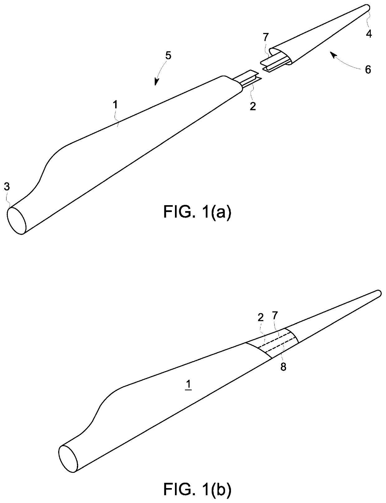
[0039]The overall wind turbine blade is shown in FIGS. 1A and 1B. The blade has an elongate structure extending in a radial sense in a finished wind turbine. The blade comprises a fairing that one is supported along its length by a spar extended along the full length of the fairing from the root end 3 to the tip 4. As shown in FIGS. 1a and 1b the fairing is in two parts with a main part 5 extending from the root for most the of the longitudinal length of the blade and tip section 6 forming the remainder of the blade. The main part 5 may be made of a number of sections joints end to end as described, for example in WO2009 / 130467.

[0040]The spar section 2 of the main part 5 connects, in use, with a tip spar section 7 for example using the technique disclosed in WO2012 / 004571 after which the joint region is covered by fairing panels 8.

[0041]As the blade invention is concerned with improvements in the tip section 6 and its method of manufacture, this will be described below with referenc...


PUM

PropertyMeasurementUnit
pressureaaaaaaaaaa
lengthaaaaaaaaaa
radiusaaaaaaaaaa

Abstract

A wind turbine blade and a method of moulding a wind turbine blade tip section. The overall wind turbine blade has an elongate structure extending in a radial sense in a finished wind turbine. The blade comprises a fairing that one is supported along its length by a spar extended along the full length of the fairing from the root end to the tip. The fairing is in two parts with a main part extending from the root for most the of the longitudinal length of the blade and the tip section forming the remainder of the blade.

Description

BACKGROUND[0001]Embodiments of the present invention relate to a wind turbine blade and a method of moulding a wind turbine blade tip section.[0002]There is a trend among offshore wind turbine blades for increasing the length of the blade. This is because the power available from a wind turbine blade increases with the square of the radius of the blade. Thus, increasing the radius of the blade produces an increase in power output which is disproportionate to the cost of turbine itself and can contribute to a lower cost of energy.[0003]However, the increase in blade size creates a number of technical challenges.[0004]One of these relates to the tip section of the aerodynamic fairing.[0005]Wind turbine blades have generally been made with fairings which extend for the full length of the wind turbine blade. These are generally made in two half shells which are bonded together on either side of an elongate spar in order to form the completed blade. In order to be able to transport longe...

Claims


Application Information

Patent Timeline
Patent Type & Authority Patents(United States)
IPC IPC(8): F03D1/06B29D99/00B29C70/34B29C70/44B29K75/00B29L31/08
CPCF03D1/0675B29C70/345B29C70/342B29D99/0028B29C70/44F05B2220/30B29L2031/085F05B2280/6003F05B2230/20F05B2230/60F05B2230/50Y02E10/721Y02P70/523B29K2075/00F05B2240/302B29C70/30F05B2230/00B29C70/304Y02P70/50Y02E10/72
Inventor HAYDEN, PAUL TREVORBEHMER, HARALD
Owner BLADE DYNAMICS LTD
Why Eureka
Try Eureka