Speed driven method for calculating torque, power and energy efficiency in the control, health assessment and maintenance of rotating equipment and turbo machinery

a technology of power and energy efficiency and torque measurement, which is applied in the direction of instruments, emergency protective circuit arrangements, force/torque/work measurement apparatus, etc., can solve the problems of insufficient power or energy conversion efficiency of the system, inability to measure/control the torque, and inability to meet the needs of real-time, in-the-field and commercial use, etc., to prolong the life of the equipment and maximize energy efficiency

Active Publication Date: 2020-06-23
QUINTANA MAURICIO F
View PDF8 Cites 10 Cited by
  • Summary
  • Abstract
  • Description
  • Claims
  • Application Information

AI Technical Summary

Benefits of technology

[0020]Other components of TLOSS can include friction, like that between a tire and a road, which will depend on a friction coefficient and the normal force between the device and the surface with friction, etc. In most cases, the normal force between the device and the friction surface does not depend on speed, but, in some cases, these normal forces, which can also be present in bearings of a rotating shaft in the form of lateral / asymmetric forces on the shaft, may depend on rotating speeds. For example, in the case of a wind turbine, the higher the speed of the rotor, the higher the lateral loads on the main bearings, which in turn increase the friction in the bearings.
[0050]E. Equip / retrofit the system with the capability to store and filter large amounts of data and with the ability to provide an existing control system (on the machine or vehicle) with driving torque, driving force or power efficiency calculations (data) to make appropriate safety, reliability, life extension, performance or energy-saving actions / strategies. (Note: the objectives of the method of the present invention include providing the control system of a rotating machine / vehicle with data related to torque and power to improve the health, life, efficiency of the machine or those who use it; in addition, the objectives include providing the operator of a machine (the driver) with a display showing the driving torque and / or the power generated and / or energy conversion efficiency, so that he can adjust his driving / operating behavior accordingly).
[0062]i. Finally, the natural decay curves can be used as a health signature of the machine / system in question. To this end, as determined by the manufacturer or user of the equipment, a new set of natural decay curves need to be produced and compared to the ones that were produced when the equipment was produced or first used (this implies repeating steps 1a to 1h every so many months or years or after a predetermined set of operating hours). The operator or manufacturer can then compare how the curve has degraded or shifted over time. If the shift is significant, it may provide unique insights into possible future failures or wear, and thus enable predictive maintenance. This will depend on the type of equipment, its use, the quality of its maintenance and expected service life, and how much historical data (natural decay curves) is available.
[0079]As is the case of the pump, the method of the present invention would allow the manufacturer and / or operator of a hydro-turbine to use historical natural decay curves to make health and maintenance / repair strategies and decisions. The method also enables the operator to determine the torque generated by the turbine and, therefore, the mechanical power generated by the turbine, which, when compared to the power (or energy) of the water entering the turbine, would then indicate the efficiency of the turbine itself and the speed at which its conversion efficiency is peaked, so the right electrical generator can be used.

Problems solved by technology

The method can be applied generally to all rotating equipment, with certain limitations related to sampling rates, the presence of lateral / eccentric loads that can change the friction in the bearings of the shaft when under load, and the ability to filter real-time data.
As noted supra, traditional torque meters are not appropriate for real-time, in-the-field, and commercial uses, because of reliability issues and the cost of such devices.
However, this approach would not yield the true and, therefore, maximum torque applied TIN because it does not account for the losses TLOSS in the system, which makes it inadequate to measure / control the torque, power or energy conversion efficiency of the system.

Method used


Image

  • Speed driven method for calculating torque, power and energy efficiency in the control, health assessment and maintenance of rotating equipment and turbo machinery
  • Speed driven method for calculating torque, power and energy efficiency in the control, health assessment and maintenance of rotating equipment and turbo machinery
  • Speed driven method for calculating torque, power and energy efficiency in the control, health assessment and maintenance of rotating equipment and turbo machinery

Examples


Embodiment Construction

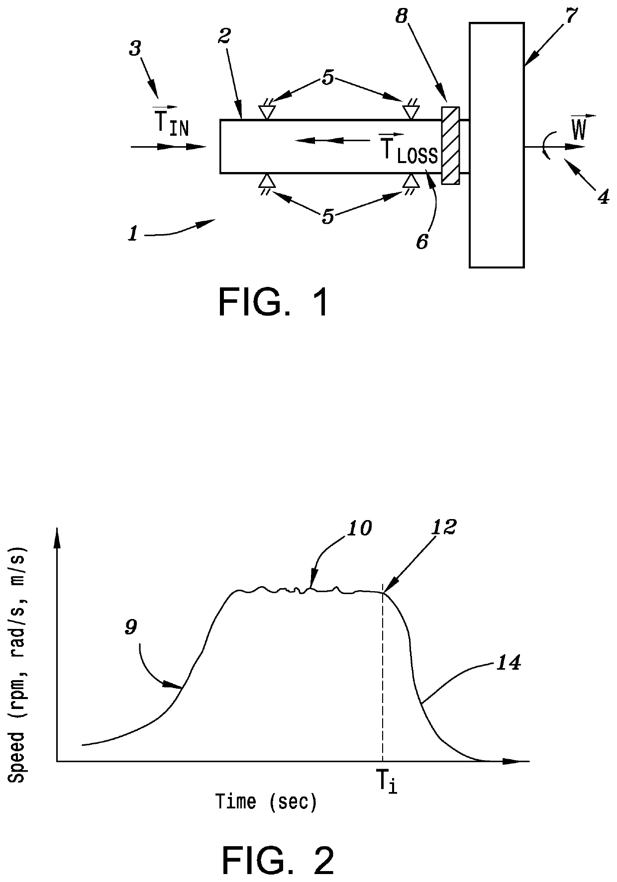
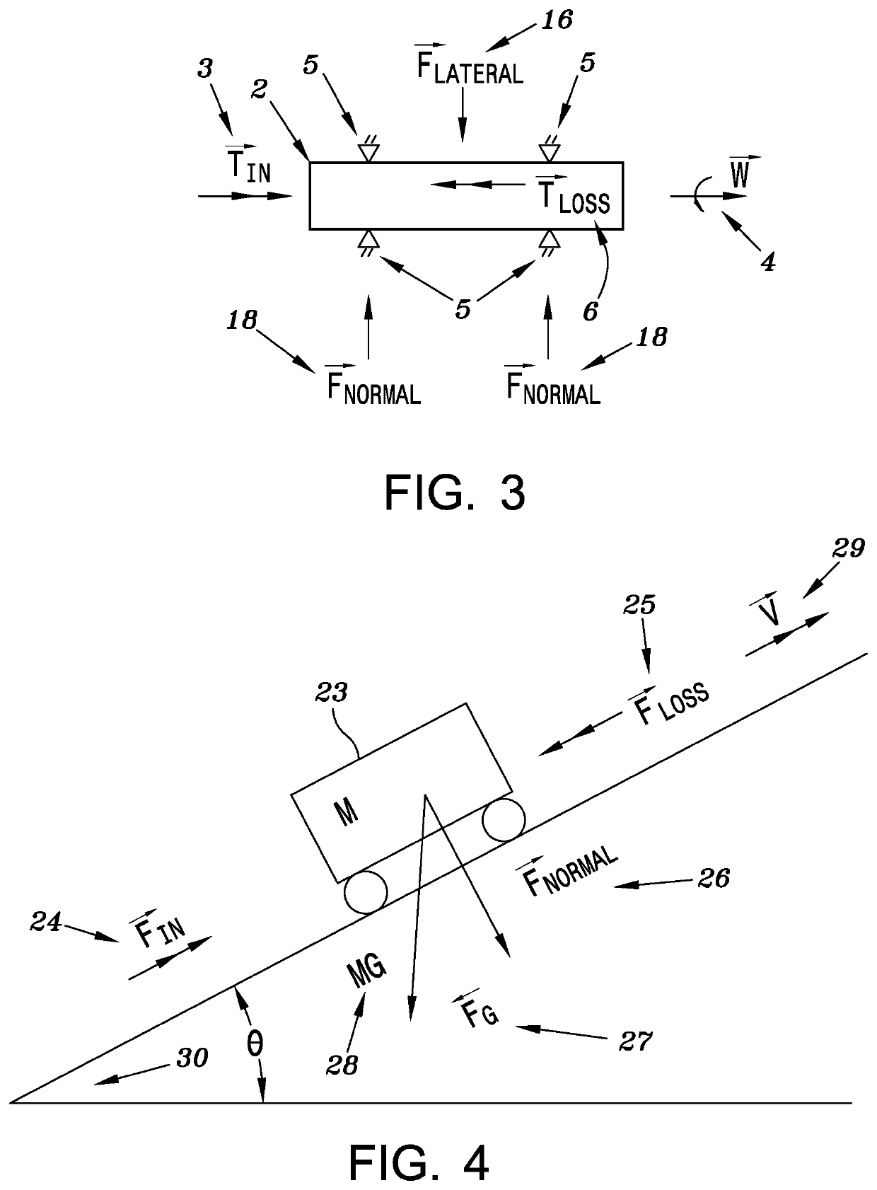
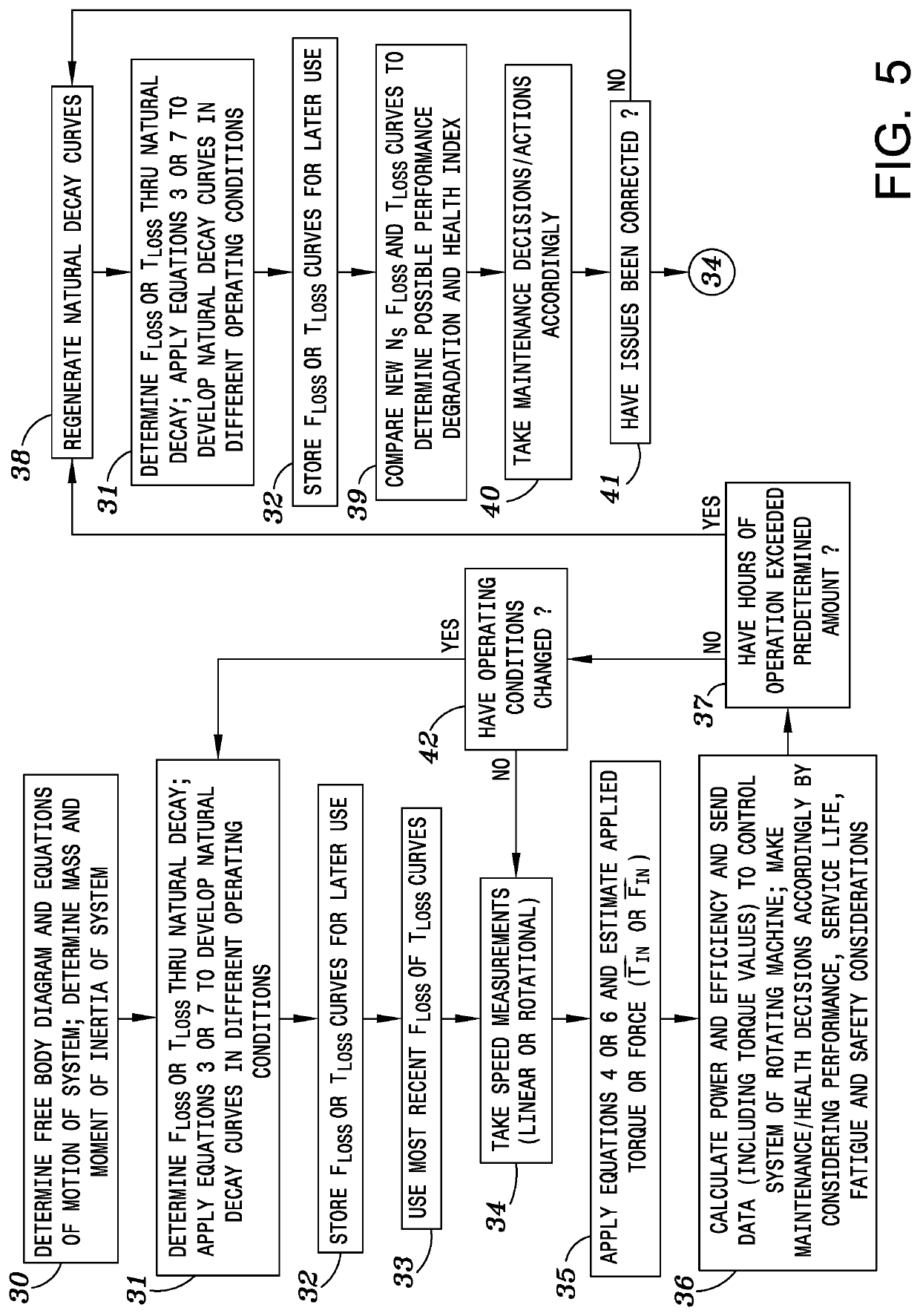
[0086]The present invention is to be used as a method to measure and manage torque and efficiency in rotating equipment, including turbo machinery. The method can be used as an input or as an upgrade to a control system of existing machines or as an improved and integral part of control systems for new rotating machinery installations. The method relies on the discrete application of the equations of motion of the machine, the measurement of, at least, the rotating or linear speed of the machine, the development and storage of the natural decay curves of the machine at specific speeds in normal operating conditions, and, in certain circumstances, as described earlier, the measurement of the inclination or altitude of the machine, when such factors need to be used to correct the equations of motion for the effects of gravity or air density, respectively. Furthermore, the method can be used to create a history of the mechanical loads (torque) the machine was subjected to in order to m...


PUM

PropertyMeasurementUnit
weightaaaaaaaaaa
torqueaaaaaaaaaa
energy efficiencyaaaaaaaaaa

Abstract

Method for measuring torque in rotating-equipment, turbo-machinery, pumps, turbines, and compressors. The measured torque can be used as an input to control torque, power, or energy efficiency. The method can also measure force (or torque) in traversing-machinery or vehicles such as automobiles, ships, aircraft, bicycles and motorcycles. The method takes real-time rotating (or linear) speed measurements, applies the discrete form of equations of motion, captures the natural decay curve(s) of the machine to estimate the torque (or force) associated with the losses of the power sink, and then solves for the driving torque of the power source. The method relates to monitoring and control systems used to safely and efficiently operate rotating-equipment and traversing-machinery. The method can be used to determine a health index of a machine to make predictive and corrective maintenance, reliability, performance, safety, and efficiency-related decisions. It is accurate, robust, lightweight, space-saving, and low cost.

Description

FIELD OF THE INVENTION[0001]The present invention relates to a method for measuring torque in rotating equipment, including turbo machinery, for both steady and unsteady state conditions, where the measured torque can be used as an input to control torque and / or maximize energy efficiency. The method is mainly based on taking real-time rotating (or linear) speed measurements and applying the discrete form of the equations of motion, where the natural decay curves of the rotating machine are used to estimate the torque associated with the losses of the power sink and then used to solve for the driving torque of the power source. The method can be used to measure the mechanical load on a shaft in rotating equipment like turbo machinery, which includes fans, pumps, gas turbines, aero turbines, wind turbines, reciprocating engines, hydro turbines, steam turbines, helicopter fans, marine propulsion and gas compressors, along with auxiliary equipment attached to them, including electric g...

Claims


Application Information

Patent Timeline
Patent Type & Authority Patents(United States)
IPC IPC(8): G01L3/26G01L5/00H02H7/08H02H1/00
CPCG01L3/26H02H7/0833G01L5/0061H02H1/0007
Inventor QUINTANA, MAURICIO F.
Owner QUINTANA MAURICIO F
Why Eureka
Try Eureka