Switching power supply

a power supply and switch technology, applied in the direction of electric variable regulation, process and machine control, instruments, etc., can solve the problems of insufficient output current, insufficient dead time to handle the sharp increase in discontinuous dead time, etc., to prolong the dead time and reduce the conversion efficiency

Active Publication Date: 2020-06-23
FDK CORP
View PDF7 Cites 0 Cited by
  • Summary
  • Abstract
  • Description
  • Claims
  • Application Information

AI Technical Summary

Benefits of technology

[0007]A switching power supply includes an insulated transformer including a primary-side coil and a secondary side coil, a full-bridge circuit that converts input DC power into AC power and outputs the AC power to the primary-side coil, an output circuit that converts AC power input from the secondary-side coil into DC power and outputs the DC power, and a control circuit that controls the full-bridge circuit by using a phase shift method based on voltage output by the output circuit, and when a measured value of the amount of phase shift determined from at least one of the voltage and current output by the output circuit is smaller than a theoretical value of the amount of phase shift corresponding to the switching power supply operating in a continuous current mode, the control circuit prolongs dead time used in the full-bridge circuit in accordance with the difference between the measured value and the theoretical value.
[0008]The switching power supply includes the full-bridge circuit controlled by using the phase shift method, and the control circuit controls the amount of phase shift to output desired output voltage. In this process, the control circuit determines the measured value of the amount of phase shift from the output circuit in the cycle of switching control that controls the full-bridge circuit. The control circuit further calculates the theoretical value of the amount of phase shift corresponding to the switching power supply operating in the continuous current mode and compares the measured value of the amount of phase shift with the theoretical value thereof. The control circuit then determines that the switching power supply operates in the discontinuous current mode when the measured value of the amount of phase shift has decreased to a value smaller than the theoretical value and prolongs the dead time used in the full-bridge circuit in accordance with the difference between the theoretical value and the measured value.
[0009]The thus configured embodiments of the present disclosure allow determination of the current mode of the switching power supply and handling of a sharp increase in the dead time necessary for establishment of ZVS in the discontinuous current mode. The present disclosure therefore provides an advantageous effect of providing a switching power supply that can appropriately set the dead time also in the discontinuous current mode to suppress a decrease in the conversion efficiency.

Problems solved by technology

However, in the related art described above, the resonance completion period calculated based on the characteristics of the resonant circuit, the output current, and other factors is not long enough to handle the sharp increase in the dead time in the discontinuous current mode.
That is, in the related art described above, even when the dead time is continuously prolonged in accordance with a decrease in the output current, the prolonged dead time is insufficient as the dead time in which ZVS is established.

Method used


Image

  • Switching power supply
  • Switching power supply
  • Switching power supply

Examples


Embodiment Construction

[0019]Embodiments of the present disclosure will be described below in detail with reference to the drawings.

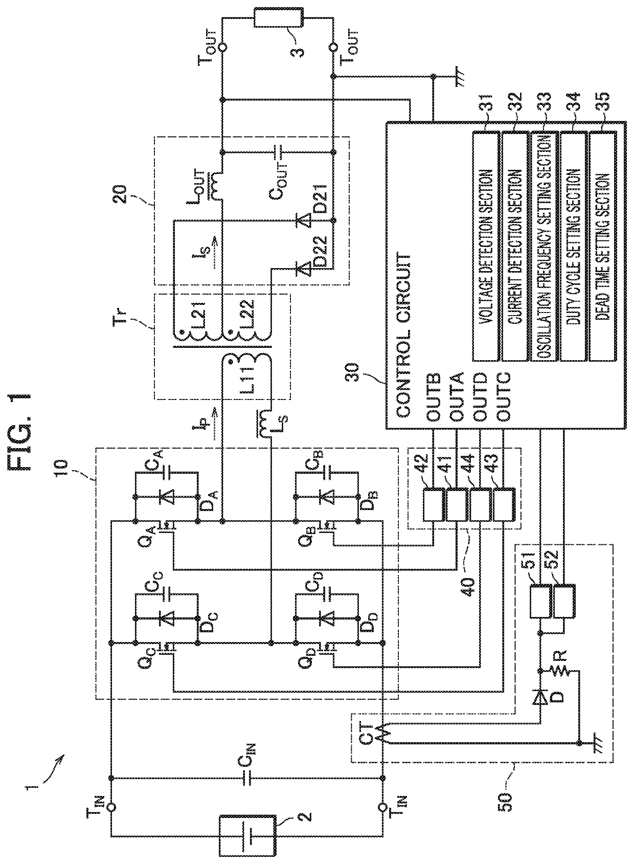
[0020]FIG. 1 is a circuit diagram showing the configuration of a switching power supply 1 according to the present disclosure. In the present embodiment, the switching power supply 1 is what is called a DC-DC converter in which an external power supply 2 is connected to two input terminals TIN and an external load 3 is connected to two output terminals TOUT so that DC input voltage VIN input from the external power supply 2 is converted into desired voltage and stable DC output voltage VOUT is output to the external load 3. The switching power supply 1 includes an input capacitor CIN, a full-bridge circuit 10, an insulated transformer Tr, a resonant coil Ls, an output circuit 20, a control circuit 30, an insulation circuit 40, and a current detection circuit 50.

[0021]The input capacitor CIN has first and second ends connected to the two input terminals TIN, respectively, and ...


PUM


Abstract

A switching power supply includes an insulated transformer, a full-bridge circuit which converts input DC power into AC power and outputs the AC power to a primary-side coil, an output circuit which converts AC power input from secondary-side coils into DC power and outputs the DC power, and a control circuit which controls the full-bridge circuit by using a phase shift method based on voltage output by the output circuit. When a measured value of the amount of phase shift determined from at least one of the voltage and current output by the output circuit is smaller than a theoretical value of the amount of phase shift corresponding to the switching power supply operating in a continuous current mode, the control circuit prolongs dead time used in the full-bridge circuit in accordance with the difference between the measured value and the theoretical value.

Description

BACKGROUNDTechnical Field[0001]The present disclosure relates to a switching power supply.Description of the Related Art[0002]As one power converter that converts input voltage into desired voltage and outputs the converted voltage, a switching power supply using a full-bridge circuit is widely used. For example, Japanese Patent Nos. 5,866,614 (Japanese Publication No. 2016-111805) and 3,706,852 (Japanese Publication No. 2004-140913) each disclose a switching power supply that serves as a DC-DC converter that converts input DC voltage into AC voltage in a full-bridge circuit, supplies the AC voltage via an insulated transformer to an output circuit, converts the AC voltage back into DC voltage in the output circuit, and outputs the DC voltage.[0003]In the related art described in Japanese Patent Nos. 5,866,614 and 3,706,852, a plurality of switching elements provided in a full-bridge circuit are controlled by using what is called a phase shift method in such a way that switching los...

Claims


Application Information

Patent Timeline
Patent Type & Authority Patents(United States)
IPC IPC(8): H02M3/337H02M3/335H02M1/08H02M1/00H02M1/38
CPCH02M1/083H02M3/33569H02M3/3376H02M2001/0009H02M1/38H02M1/0038H02M1/0058H02M3/33573H02M3/01H02M1/0009Y02B70/10
Inventor HAMADA, KENJISATO, TADASHIFUKUI, NORIO
Owner FDK CORP
Why Eureka
Try Eureka