Vertebral implant, device for vertebral attachment of the implant and instrumentation for implantation thereof

a technology for vertebrae and implants, applied in the field of vertebral implants, can solve the problems of degradation of vertebrae, intervertebral discs, vertebrae (either partially or completely), and/or deformation of vertebrae, and achieve the effect of convenient implanting

Active Publication Date: 2020-07-07
LDR MEDICAL SAS
View PDF479 Cites 2 Cited by
  • Summary
  • Abstract
  • Description
  • Claims
  • Application Information

AI Technical Summary

Benefits of technology

[0010]Various embodiments of the present application are configured for removing or reducing at least one of the drawbacks of the prior art, including those from among the drawbacks discussed above, for example by proposing a vertebral implant, such as for corpectomy, that has an adaptable size, that is easy to implant and that reliably attaches to the vertebral structures adjacent to the replaced vertebral segment.
[0011]Various of such goals, for example, may be achieved with various embodiments of this disclosure, such as implants for corpectomy or fusion, intended to be inserted into the rachis according to at least one approach route, for replacing a vertebral segment, the implant extending along a vertical axis, between upper and lower surfaces of the implant each intended to be placed in contact with a respectively upper and lower structure, of said vertebral segment. In various embodiments, the implant includes at least one first body and at least one second body each having at least mutual fitting means in order to allow assembling of said bodies by sliding along a sliding axis, and at least one locking means retained in or on at least one of the bodies, and at least one abutment portion of which is laid out for passing from a so-called open position, allowing sliding for the assembling of said bodies, to a so-called closed position locking said bodies assembled together by the contact between at least said abutment portion and at least one abutment of at least one of said bodies, said abutment being oriented not parallel to the sliding axis and said abutment portion passing from the open position to the closed position elastically by flexure or torsion, by means of at least one flexible portion of the locking means allowing withdrawal of said abutment portion of the locking means in an open position during the sliding of the bodies on the one hand and elastic return of said abutment portion into the closed position when it is found facing said abutment of said body on the other hand.
[0016]According to some other features, in some embodiments said mating faces of the bodies are tilted relatively to the plane(s) of the upper and lower surfaces of the implant, so that the assembling of the bodies is accomplished by starting from their respective side with a lower height and the sliding occurs according to a tilted plane allowing restoration of a determined height to the implant and compression of the implant.
[0018]According to some other features, in some embodiments the mutual fitting means of said mating faces of the bodies prevent the movements of the two bodies along at least one direction not parallel to the sliding axis.
[0022]According to some other features, in some embodiments the bone anchoring means are locked in the implant with at least one locking means retained in at least one of the bodies and at least one abutment portion of which is laid out for passing from a so-called open position allowing the sliding of the bone anchoring means in their passage to a so-called closed position locking, preventing sliding of the bone anchoring means by the contact between at least said abutment portion and at least one abutment of the bone anchoring means, said abutment being oriented not parallel to the path of said passage and said abutment portion passing from the open position to the closed position, elastically by flexure or by torsion, by means of at least one flexible portion of the locking means allowing withdrawal of said abutment portion of the locking means in an open position during the sliding of the bone anchoring means on the one hand and, elastic return of said abutment portion into a closed position when it is found facing said abutment of the bone anchoring means on the other hand.
[0024]According to some other features, in some embodiments at least one posterior portion of the curved plate includes at least one abutment mating an abutment in the passage of the implant for immobilizing the bone anchoring means at the end of the deployment, said curved plate including, on at least one posterior portion, a slot crossing the whole of its thickness giving the possibility of providing elasticity to this posterior portion and the possibility of mutual engagement of these abutments and their clearing upon withdrawal of the bone anchoring means.

Problems solved by technology

A problem in the field of vertebral implants and notably of corpectomy cages sometimes relates to the deployment of an implant capable of replacing a vertebral segment, sometimes with a large size, at least in height, for a corpectomy cage since the vertebral segment may correspond to all or part of at least one vertebral body and / or at least one intervertebral disc.
Indeed, certain pathologies, notably cancer diseases, may result in a degradation of the vertebral bodies (either partly or completely) and / or of the intervertebral discs.
A problem related to the height of the implants sometimes involves the stabilization of the implant against the vertebral structures between which it is inserted.
Further, the anchoring of the implant is generally preferable to simple notches which generally only limit the risk of movement but do not enhance reliable immobilization.
These solutions have the drawbacks of relying on generally complex and costly mechanisms, which often make the implant and / or the vertebrae fragile since the distraction obtained by the implant during its expansion often does not give the possibility of estimating the exerted force because the surgeon often does not feel enough the force he / she generates during the distraction (such that the implants sometimes collapse in the vertebrae).
Further, they often provide a reduced grafting space, not allowing the addition of a bone graft or substitute, sufficient for quality arthrodesis.
Similarly, such implants are often made of metallic material, which does not allow viewing of the bone growth into the cage during inspections by post-operative imaging.
These types of expandable cages are often incompatible with notches or teeth for stabilization (since the latter reduce the actual distraction capability, interfere with the positioning and risk making the adjacent vertebral structures fragile) and / or with anchoring (since the cages generally do not provide a sufficiently wide structure for retaining an anchoring means).
Moreover, anchoring with screws may prove to be tedious to set into place and requires an overly invasive approach.
Other problems, often related to expandable cages in situ and to the drawbacks of certain of the solutions of the prior art, sometimes relate to the insertion of the implant into the rachis, which is generally difficult on the one hand and the assembling and locking of the various elements of the implant, which have to be sufficiently easy and reliable for providing a solution limiting the dislocation risks of the implant on the other hand.
Another problem in the field relates to invasivity and in particular to accessing the intervertebral spaces (discal spaces) which is often particularly delicate because of the congestion, notably because of the presence of blood vessels and nerves in the neighborhood of the intervertebral space, as well as the proximity of the spinal cord.
Another problem for bone anchoring means often related to the drawbacks of certain of the solutions of the prior art, sometimes relates to the removal of the bone anchoring means and / or of the implant, since removal is generally impossible or difficult.

Method used


Image

  • Vertebral implant, device for vertebral attachment of the implant and instrumentation for implantation thereof
  • Vertebral implant, device for vertebral attachment of the implant and instrumentation for implantation thereof
  • Vertebral implant, device for vertebral attachment of the implant and instrumentation for implantation thereof

Examples


Embodiment Construction

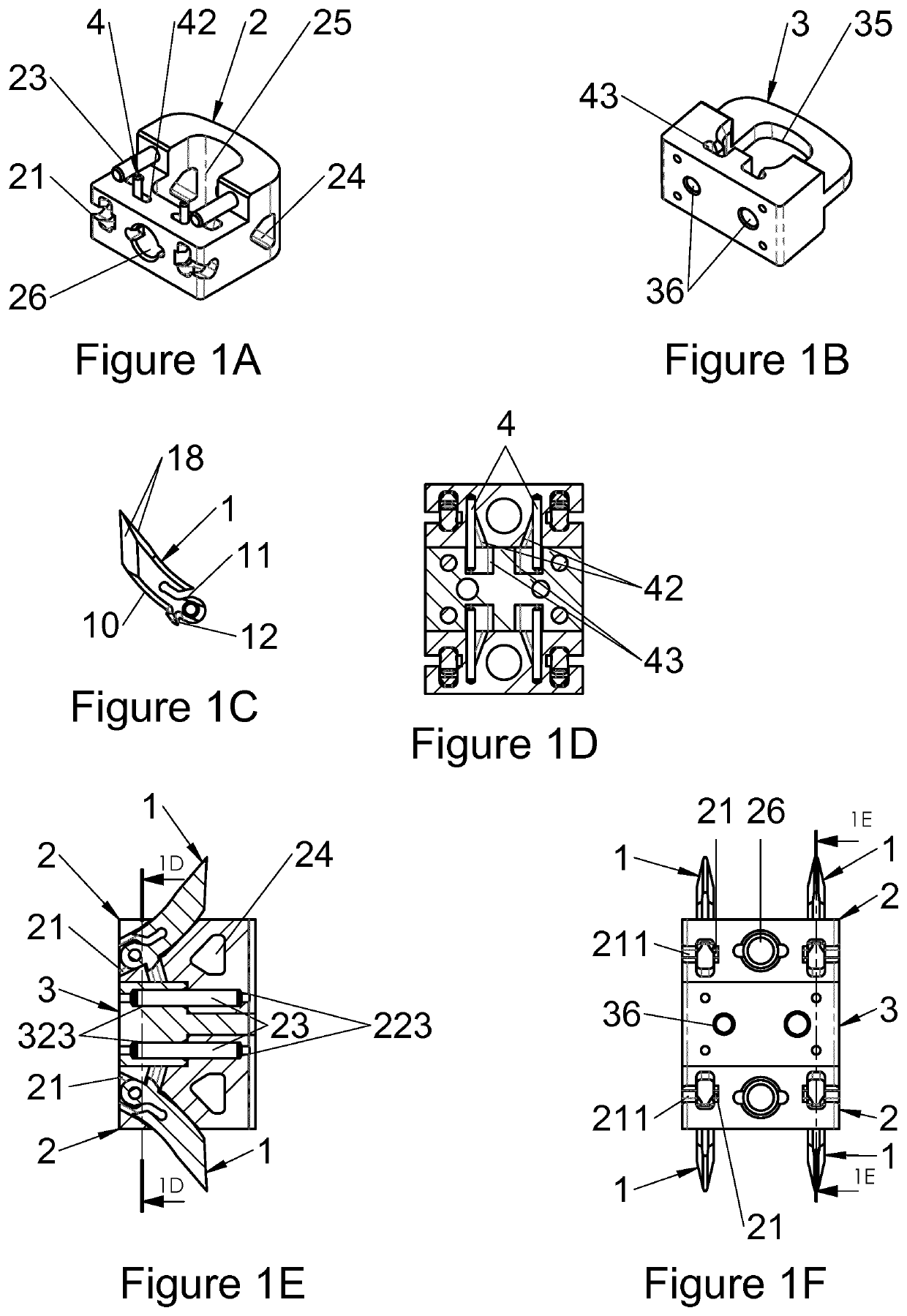
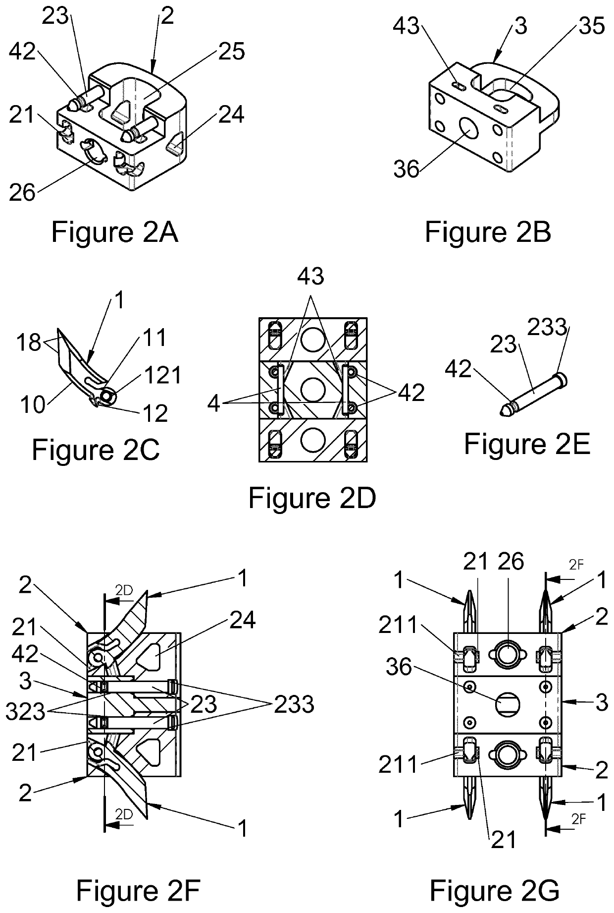
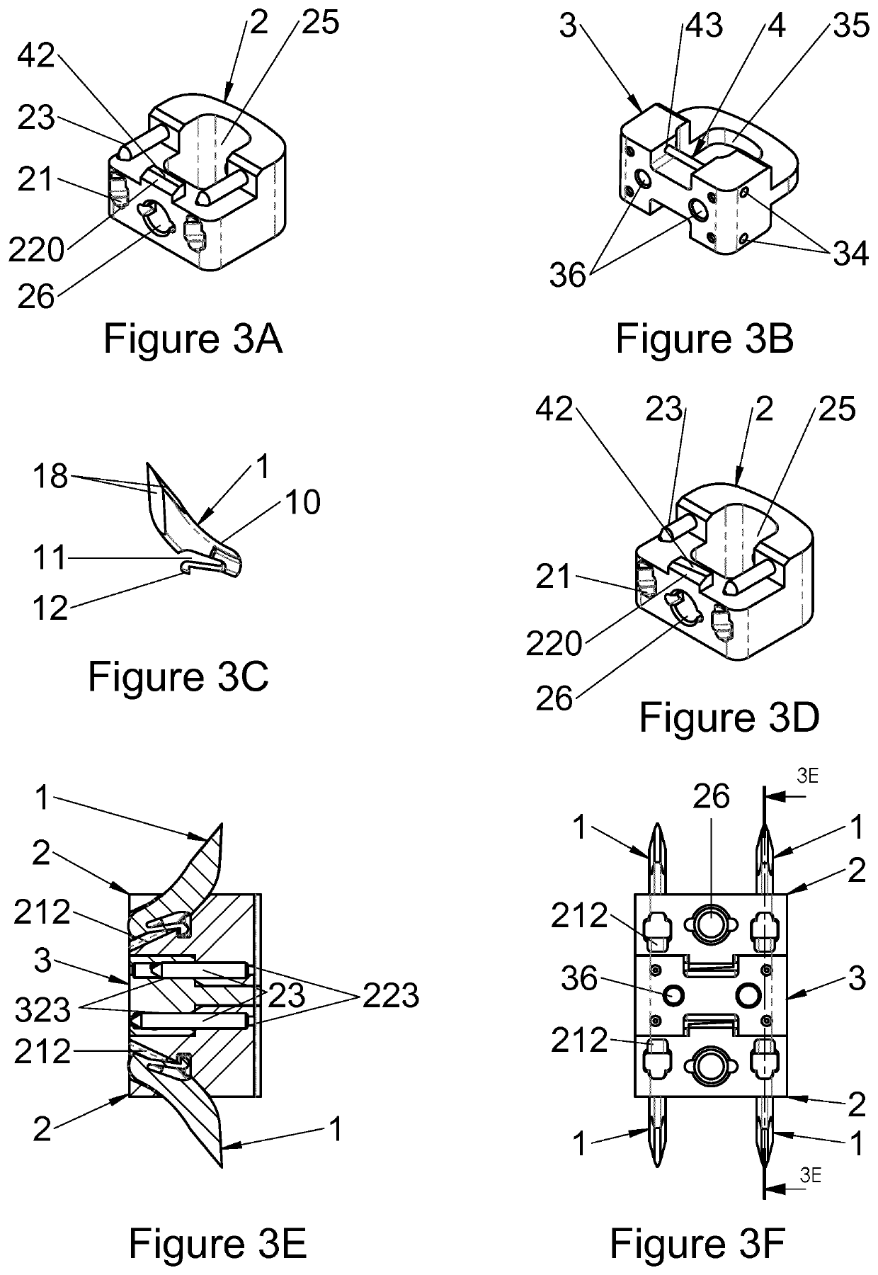
[0079]The present application relates to vertebral implants, for example for corpectomy involving ablation of a vertebral segment and insertion of an implant replacing the removed tissues. The present application also describes various bone anchoring means (or attachment devices) for implants in general, for example of the type of those of the present application. These attachment devices are also designated in the present disclosure with the terms of “anchor” or “anchoring” or further “attachment means”. The present disclosure also relates to implantation instrumentation for inserting an implant and to instrumentation for attaching implants. The term of “vertebral segment” is used in the present description in its generally accepted meaning of “a portion of the rachis” since it may correspond to all or part of at least one vertebral body and / or at least one intervertebral disc. Indeed, corpectomy may concern at least one entire vertebral body, or even an entire vertebra and its adj...


PUM


Abstract

The present invention relates to a vertebral implant, in particular for corpectomy, to a device for attaching a vertebral implant and to implantation instrumentation, the implant including at least one first body (2) and at least one second body (3) each having at least one face having shapes and dimensions mating those of at least one face of another body (3, 2) and forming mutual fitting means, in order to allow assembling of said bodies (2, 3) by sliding along a sliding axis and, on the other hand, at least one locking means (4) retained in at least one of the bodies (2, 3) and at least one abutment portion of which is laid out for passing from a so-called open position, allowing sliding for the assembling of said bodies (2, 3), to a so-called closed position, locking said bodies (2, 3) assembled together by the contact between at least said abutment portion and at least one abutment (42, 43) of at least one of said bodies (2, 3), said abutment (42, 43) being oriented not parallel to the sliding axis and said abutment portion passing from the open position to the closed position elastically by flexure or torsion.

Description

CROSS-REFERENCE TO RELATED APPLICATIONS[0001]This application is a National Stage entry of International Application No. PCT / EP2015 / 060001 filed May 6, 2015, which claims priority in accordance with 35 U.S.C. §§ 365 and 120 to U.S. patent application Ser. No. 14 / 638,746 filed Mar. 4, 2015, and priority is claimed in accordance with 35 U.S.C. §§ 365 and 119 to French Patent Application No. FR1454102 filed in FRANCE on May 6, 2014, through International Application No. PCT / EP2015 / 060001 and U.S. patent application Ser. No. 14 / 638,746. International Application No. PCT / EP2015 / 060001 and U.S. patent application Ser. No. 14 / 638,746 are incorporated herein by reference.TECHNICAL FIELD OF THE INVENTION[0002]The present application relates to the field of vertebral implants, including corpectomy cages and intersomatic cages, intended to replace a vertebral segment, i.e. all or part of at least one vertebral body and / or at least one intervertebral disc. The present application also relates t...

Claims


Application Information

Patent Timeline
Patent Type & Authority Patents(United States)
IPC IPC(8): A61F2/44A61F2/46A61B17/86A61B17/88A61F2/30
CPCA61F2/4455A61F2/4611A61B17/8872A61F2/447A61F2/442A61F2/4637A61F2/4465A61F2/44A61B17/86A61F2/4425A61F2002/30387A61F2/4603A61F2002/30841A61F2220/0016A61F2002/30579A61F2002/30505A61F2002/30481A61F2002/4629A61F2002/448A61F2002/30604A61F2002/30593
Inventor AMEIL, MARCLEE, DANIEL D.CHO, PAUL HENRY
Owner LDR MEDICAL SAS
Why Eureka
Try Eureka