
Magnetic tape apparatus

a technology of magnetic tape and tape, which is applied in the direction of recording on magnetic tape, maintaining head carrier alignment, instruments, etc., can solve the problems of not revealing specific means for improving the reproducing quality of the magnetic tape apparatus, and the reproducing quality tends to be hardly improved, so as to achieve high reproducing quality

Active Publication Date: 2020-07-07
FUJIFILM CORP
View PDF16 Cites 42 Cited by
  • Summary
  • Abstract
  • Description
  • Claims
  • Application Information

AI Technical Summary

Benefits of technology

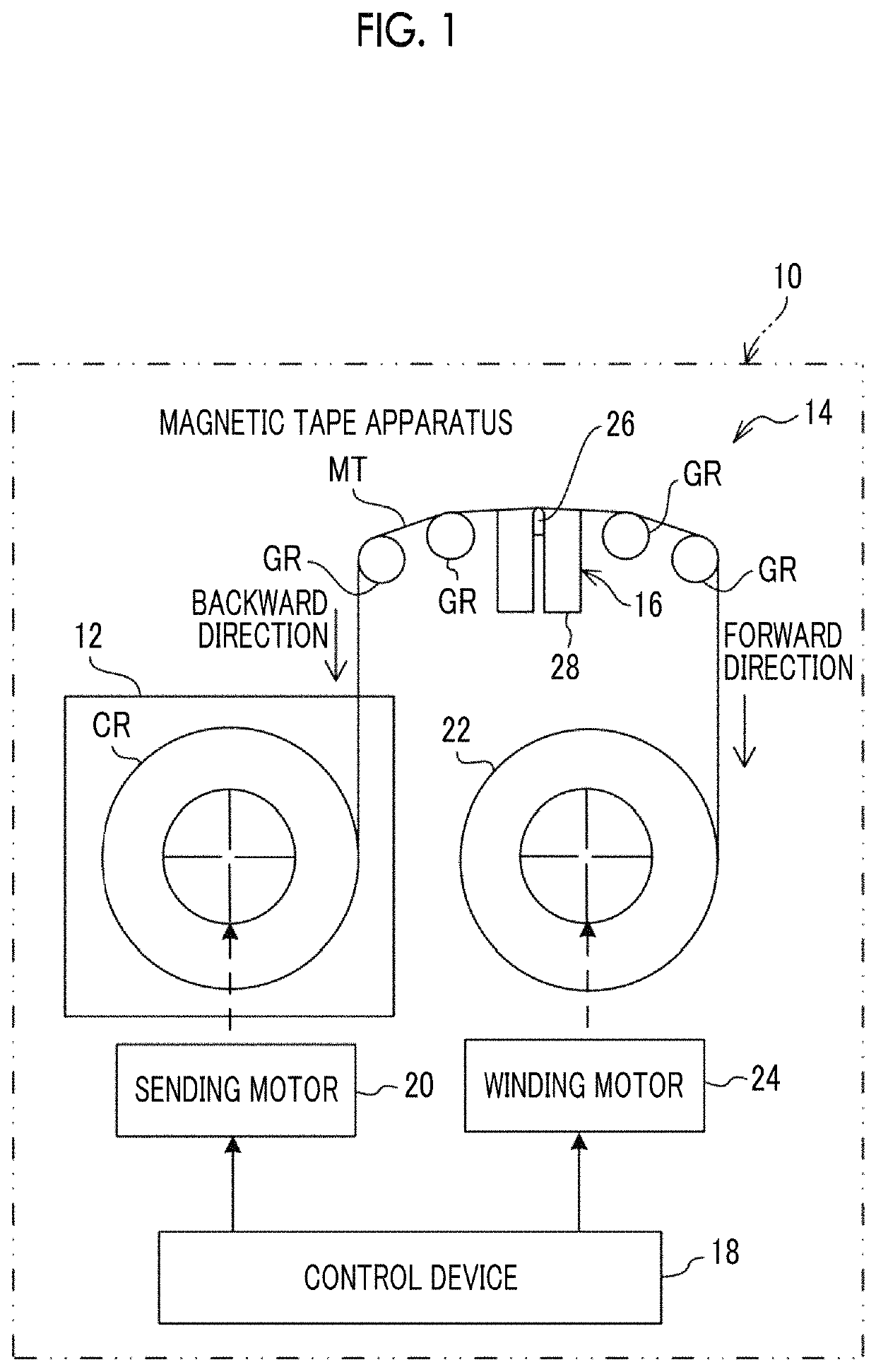
[0005]In JP2016-110680A and JP2011-134372A, studies regarding a magnetic disk apparatus are conducted. Meanwhile, in recent years, a magnetic tape is receiving attention as a data storage medium for storing a large content of data for a long period of time. However, the magnetic tape apparatus is a sliding type apparatus in which data reading (reproducing) is performed due to a contact and sliding between the magnetic tape and a reading element. Accordingly, a relational position between the reading element and a reading target track easily changes during the reproducing, and the reproducing quality tends to be hardly improved, compared to a magnetic disk apparatus. U.S. Pat. No. 7,755,863B discloses the description regarding the magnetic tape apparatus (tape drive), but does not disclose specific means for improving the reproducing quality of the magnetic tape apparatus.
[0006]One aspect of the invention provides a magnetic tape apparatus capable of improving the reproducing quality.
[0019]According to one aspect of the invention, it is possible to provide a magnetic tape apparatus capable of reproducing data recorded on a magnetic tape with high reproducing quality.

Problems solved by technology

Accordingly, a relational position between the reading element and a reading target track easily changes during the reproducing, and the reproducing quality tends to be hardly improved, compared to a magnetic disk apparatus.
U.S. Pat. No. 7,755,863B discloses the description regarding the magnetic tape apparatus (tape drive), but does not disclose specific means for improving the reproducing quality of the magnetic tape apparatus.

Method used


Image

  • Magnetic tape apparatus
  • Magnetic tape apparatus
  • Magnetic tape apparatus

Examples


example 1

[0293]A list of each layer forming composition is shown below.

[0294]List of Magnetic Layer Forming Composition

[0295]Magnetic Liquid[0296]Ferromagnetic powder (see Table 5): 100.0 parts[0297]Oleic acid: 2.0 parts[0298]A vinyl chloride copolymer (MR-104 manufactured by Kaneka Corporation): 10.0 parts[0299]SO3Na group-containing polyurethane resin: 4.0 parts[0300](Weight-average molecular weight: 70,000, SO3Na group: 0.07 meq / g)[0301]An amine-based polymer (DISPERBYK-102 manufactured by BYK Additives & Instruments): 6.0 parts

[0302]Methyl ethyl ketone: 150.0 parts[0303]Cyclohexanone: 150.0 parts

[0304]Abrasive Solution[0305]α-Alumina: 6.0 parts[0306](Brunauer-Emmett-Teller (BET) specific surface area: 19 m2 / g, Mohs hardness: 9)[0307]SO3Na group-containing polyurethane resin: 0.6 parts[0308](Weight-average molecular weight: 70,000, SO3Na group: 0.1 meq / g)[0309]2,3-dihydroxynaphthalene: 0.6 parts[0310]Cyclohexanone: 23.0 parts

[0311]Projection Formation Agent Liquid[0312]Colloidal silica: 2...


PUM

PropertyMeasurementUnit
photoelectron take-off angleaaaaaaaaaa
take-off aaaaaaaaaa
energy resolutionaaaaaaaaaa

Abstract

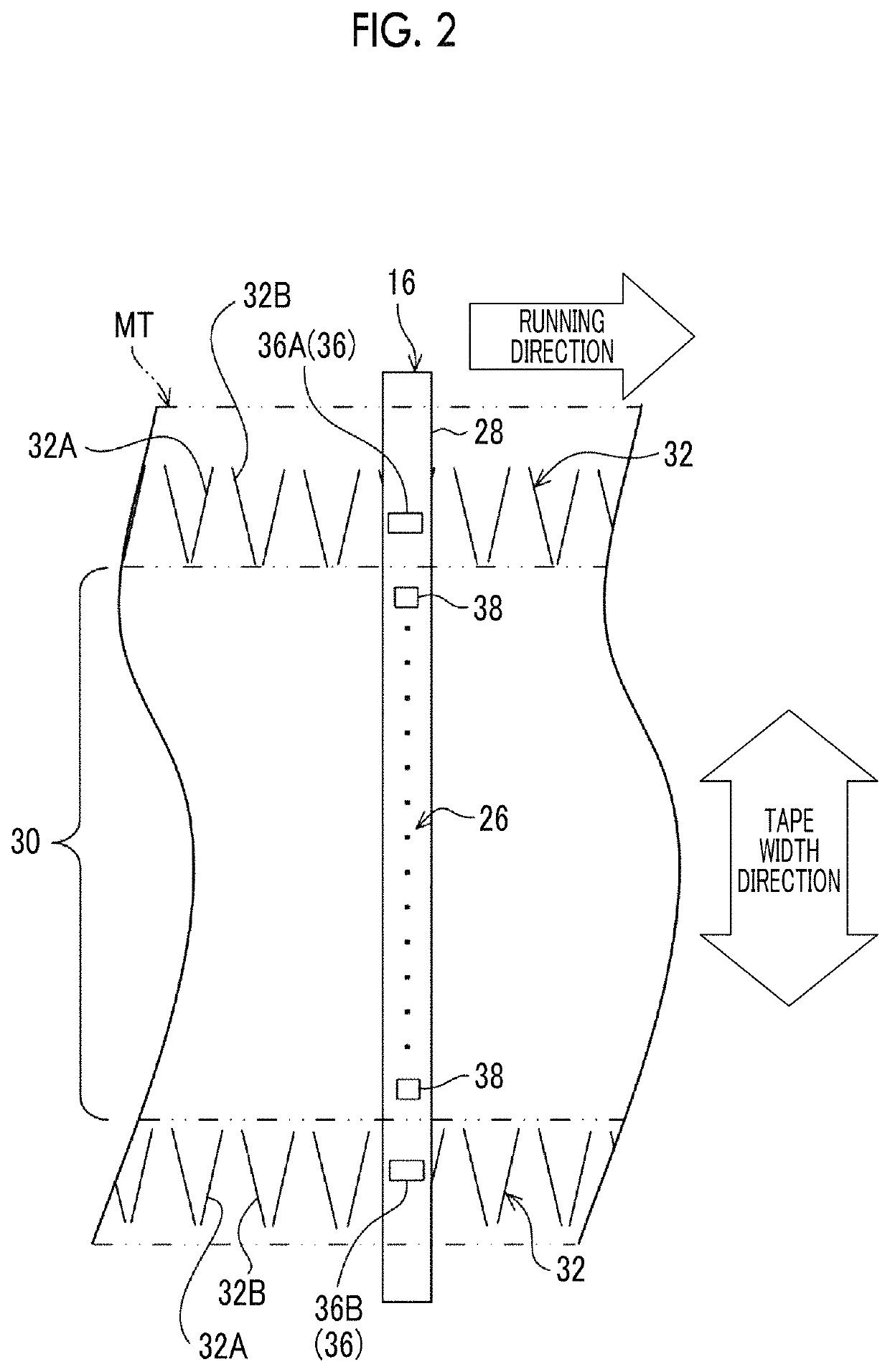
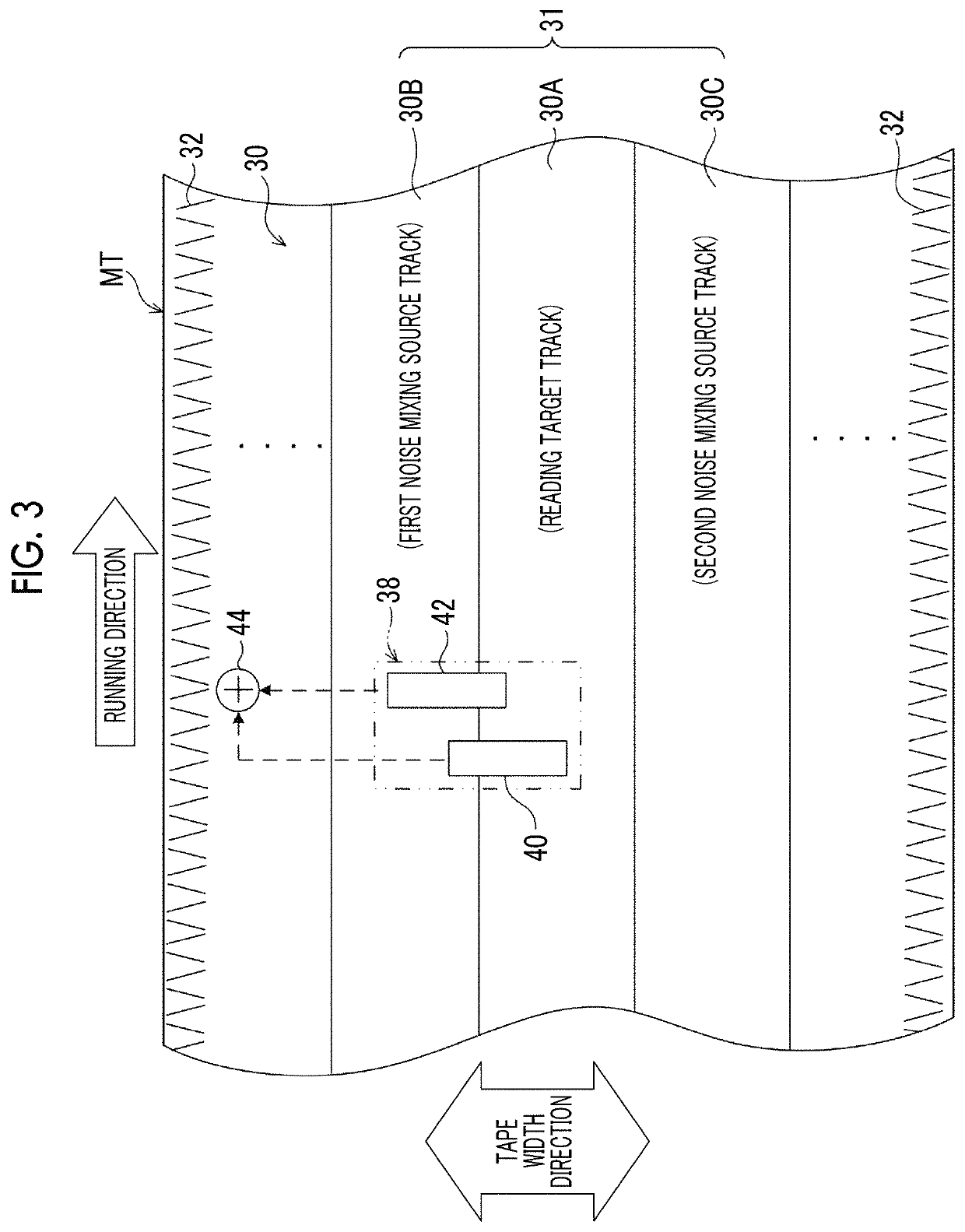
A magnetic tape apparatus includes a magnetic tape, a reading element unit and an extraction unit, in which a C-H derived C concentration calculated from a C-H peak area ratio of C1s spectra obtained by X-ray photoelectron spectroscopic analysis performed on the surface of the magnetic layer of the magnetic tape at a photoelectron take-off angle of 10 degrees is equal to or greater than 45 atom %, and the extraction unit performs a waveform equalization process according to a deviation amount between positions of the magnetic tape and the reading element unit, with respect to each reading result for each reading element, to extract data derived from the reading target track from the reading result.

Description

CROSS-REFERENCE TO RELATED APPLICATIONS[0001]This application claims priority under 35 U.S.C 119 to Japanese Patent Application No. 2018-125584 filed on Jun. 29, 2018 and Japanese Patent Application No. 2019-100046 filed on May 29, 2019. The above application is hereby expressly incorporated by reference, in its entirety, into the present application.BACKGROUND OF THE INVENTION1. Field of the Invention[0002]The present invention relates to a magnetic tape apparatus.2. Description of the Related Art[0003]A magnetic recording and reproducing apparatus which performs recording of data on a magnetic recording medium and / or reading (reproducing) of the recorded data is widely divided into a magnetic disk apparatus and a magnetic tape apparatus. A representative example of the magnetic disk apparatus is a hard disk drive (HDD). In the magnetic disk apparatus, a magnetic disk is used as the magnetic recording medium. Meanwhile, in the magnetic tape apparatus, a magnetic tape is used as the...

Claims


Application Information

Patent Timeline
Patent Type & Authority Patents(United States)
IPC IPC(8): G11B5/09G11B5/008G11B5/584G11B5/39
CPCG11B5/00813G11B5/3945G11B5/584G11B5/00817G11B5/5508
Inventor KASADA, NORIHITOOZAWA, EIKIMUSHA, ATSUSHI
Owner FUJIFILM CORP
Learn More