Die cushion device and method of controlling the die cushion device

a technology of die cushion and die cushion pad, which is applied in the direction of presses, manufacturing tools, etc., can solve the problems of cushion force, delay time elapse, and response delay time, and achieve the effect of increasing the responsivity of the action of the die cushion force and avoiding the increase of the cushion pad

Active Publication Date: 2020-07-14
AIDA ENG LTD
View PDF15 Cites 0 Cited by
  • Summary
  • Abstract
  • Description
  • Claims
  • Application Information

AI Technical Summary

Benefits of technology

[0015]The present invention is made in light of the above-mentioned circumstances, and an object thereof is to provide a die cushion device and a method of controlling the die cushion device, capable of increasing responsivity of action of die cushion force, and of generating desired die cushion force particularly when a cushion pad is positioned at a die cushion standby position, without greatly restricting die structure.
[0035]According to the present invention, it is possible to control pressure in a cap side (die cushion pressure generating side) fluid-pressure chamber of a fluid-pressure cylinder that generates die cushion force, before the die cushion force control starts. This enables increase in responsivity of action of the die cushion force, and enables a cushion pad not to be greatly raised from a normal die cushion standby position.

Problems solved by technology

The die cushion device described in each of Patent Literatures 1 and 2 causes a problem in that response delay time occurs by the time die cushion force increases to a preset value after a slide collides with a cushion pad (an upper die mounted to the slide collides with the cushion pad supported by a hydraulic cylinder through a material, a blank holder, and a cushion pin) while the slide of a press machine descends, and that the slide descends below an initial position (a die cushion standby position set for each die) of the cushion pad with which the slide collides, while the response delay time elapses.
In addition, while the die cushion device described in each of Patent Literatures 1 and 2 generates die cushion force by controlling hydraulic pressure in a cap side hydraulic chamber of the hydraulic cylinder, this mechanism does not enable the pressure in the cap side hydraulic chamber of the hydraulic cylinder to be controlled before the slide and the cushion pad collide with each other.
Meanwhile, in the case of a technique in which a cushion pad is put on standby at a position above a die cushion standby position by a predetermined amount, and die cushion force is increased to a setting value when the cushion pad descends to the die cushion standby position, the cushion pad needs to be raised above the die cushion standby position by the predetermined amount, whereby die structure (e.g. an upper limit position of a die stroke) is greatly restricted to have little practicability.

Method used


Image

  • Die cushion device and method of controlling the die cushion device
  • Die cushion device and method of controlling the die cushion device
  • Die cushion device and method of controlling the die cushion device

Examples


first embodiment

of First Hydraulic Circuit

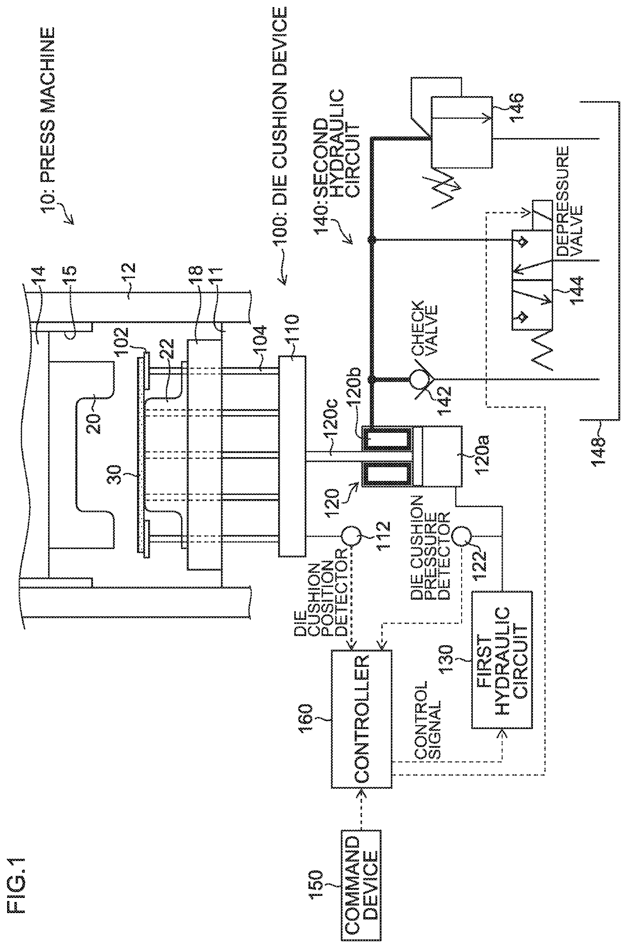
[0116]FIG. 6 is a structural diagram corresponding to the die cushion device 100′ of the second embodiment illustrated in FIG. 4, and is a structural diagram including particularly a first hydraulic circuit 130-1 of the first embodiment, corresponding to the first hydraulic circuit 130 illustrated in FIG. 1. The die cushion device 100′ illustrated in FIG. 6 includes an accumulator 149 under a gas pressure of a low pressure (e.g. 0.7 MPa), serving as a tank, instead of the tank 148 illustrated in FIG. 4, the accumulator 149 being connected to a low pressure line.

[0117]The first hydraulic circuit 130-1 of the first embodiment illustrated in FIG. 6 includes: a hydraulic pump / motor (fluid-pressure pump / motor) 130A; a servo motor (electric motor) 130B connected to a rotating shaft of the hydraulic pump / motor 130A; an angular speed detector 130C that detects angular speed (servo motor angular speed ω) of a drive shaft of the servo motor 130B; a pilot drive type c...

second embodiment

of First Hydraulic Circuit

[0132]FIG. 7 is a structural diagram corresponding to the die cushion device 100′ of the second embodiment illustrated in FIG. 4, and is a structural diagram including particularly the first hydraulic circuit 130-2 of the second embodiment.

[0133]The first hydraulic circuit 130-2 of the second embodiment illustrated in FIG. 6 includes a 4-port, 2-position proportion flow control valve (hereinafter referred to as simply a “proportion flow control valve”) 131, a solenoid changeover valve 132, a check valve 133, a pressure oil supply source with an accumulator 143A (including the hydraulic pump 143B, the electric motor 143D, and the relief valve 143F), and the like.

[0134]The die cushion pressure detector 122 for detecting pressure in the cap side hydraulic chamber 120a as well as an A port of the proportion flow control valve 131 is connected to a flow channel connected to the cap side hydraulic chamber 120a of the hydraulic cylinder 120, and a flow channel con...


PUM

PropertyMeasurementUnit
diameteraaaaaaaaaa
diameteraaaaaaaaaa
diameteraaaaaaaaaa

Abstract

A die cushion device includes a hydraulic cylinder that supports a cushion pad and generates die cushion force when the slide of the press machine descends, a first hydraulic circuit that is connected to a cap side hydraulic chamber of the hydraulic cylinder, and a second hydraulic circuit that is connected to a rod side hydraulic chamber. Before die cushion force control starts, the second hydraulic circuit of the die cushion device causes hydraulic oil in the rod side hydraulic chamber to be prevented from flowing out, and the first hydraulic circuit of the die cushion device causes the cap side hydraulic chamber to be pressurized.

Description

CROSS-REFERENCE TO RELATED APPLICATIONS[0001]This application claims priority to Japanese Patent Application No. 2015-252167 filed Dec. 24, 2015, The entire contents of which are hereby incorporated herein by reference in entirety.BACKGROUND OF THE INVENTION[0002]Field of the Invention[0003]The present invention relates to a die cushion device and a method of controlling the die cushion device, and more particularly to a technique of improving responsivity of action of cushion force.[0004]Description of the Related Art[0005]In a press machine including a die cushion device, there has been known a die cushion device that controls hydraulic pressure (die cushion force) in a cap side hydraulic chamber of a hydraulic cylinder supporting a cushion pad by using a servo motor for driving a hydraulic pump connected to cap side hydraulic chamber, or a servo valve (refer to Japanese Patent Application Laid-Open No. 2006-315074 (Patent Literature 1) and Japanese Patent Application Laid-Open No...

Claims


Application Information

Patent Timeline
Patent Type & Authority Patents(United States)
IPC IPC(8): B21D24/02B21D24/14
CPCB21D24/14B21D24/02B21D24/08B30B15/16B30B15/08
Inventor MAKABE, JUNJI
Owner AIDA ENG LTD
Why Eureka
Try Eureka