Vehicle vision system with 3D registration for distance estimation

a technology of vehicle vision and distance estimation, applied in the field of vehicle vision system, can solve the problems of sfm reliability varies, the range of use of sfm is limited to about 3 meters, and the range of sfm is very limited, so as to achieve reliable distance estimation, stable output, and greater estimation range

Active Publication Date: 2020-07-14
MAGNA ELECTRONICS INC
View PDF121 Cites 2 Cited by
  • Summary
  • Abstract
  • Description
  • Claims
  • Application Information

AI Technical Summary

Benefits of technology

[0006]The method of the present invention helps alleviate the reliability problem by first using the available frame data in a more structured environment to get more stable outputs as well as using some back-projection to reject bad or unstable outputs.
[0007]This technique is moving towards reliable depth estimation that may be competitive with camera systems with the ultrasonic sensors but with a greater range of estimation. The system of the present invention is not only applicable to wide angle optics but also to narrow angle FOV cameras, such as may be used in the side exterior rearview mirrors for lane watch or such as may be used at the vehicle windshield.

Problems solved by technology

However, given the relatively low amount of motion and different degree of motion along different optical axes, the reliability of SfM varies.
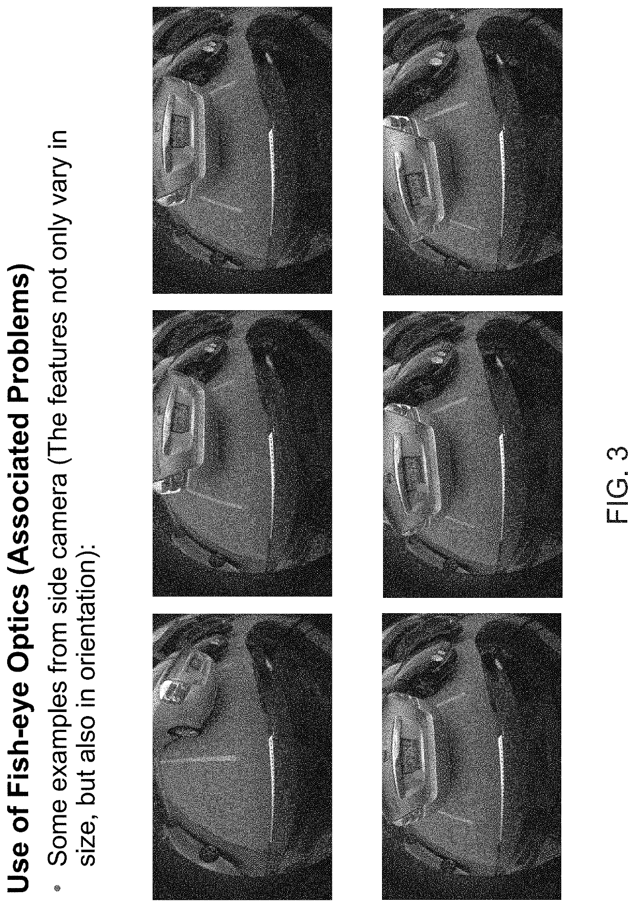
Particularly for wide field of view (FOV) optics (such as fish-eye lenses), the use of SfM is limited to about 3 meters in range and is very limited along the central area of the image where the motion flow would be along the optical axis for front and rear cameras.

Method used


Image

  • Vehicle vision system with 3D registration for distance estimation
  • Vehicle vision system with 3D registration for distance estimation
  • Vehicle vision system with 3D registration for distance estimation

Examples


Embodiment Construction

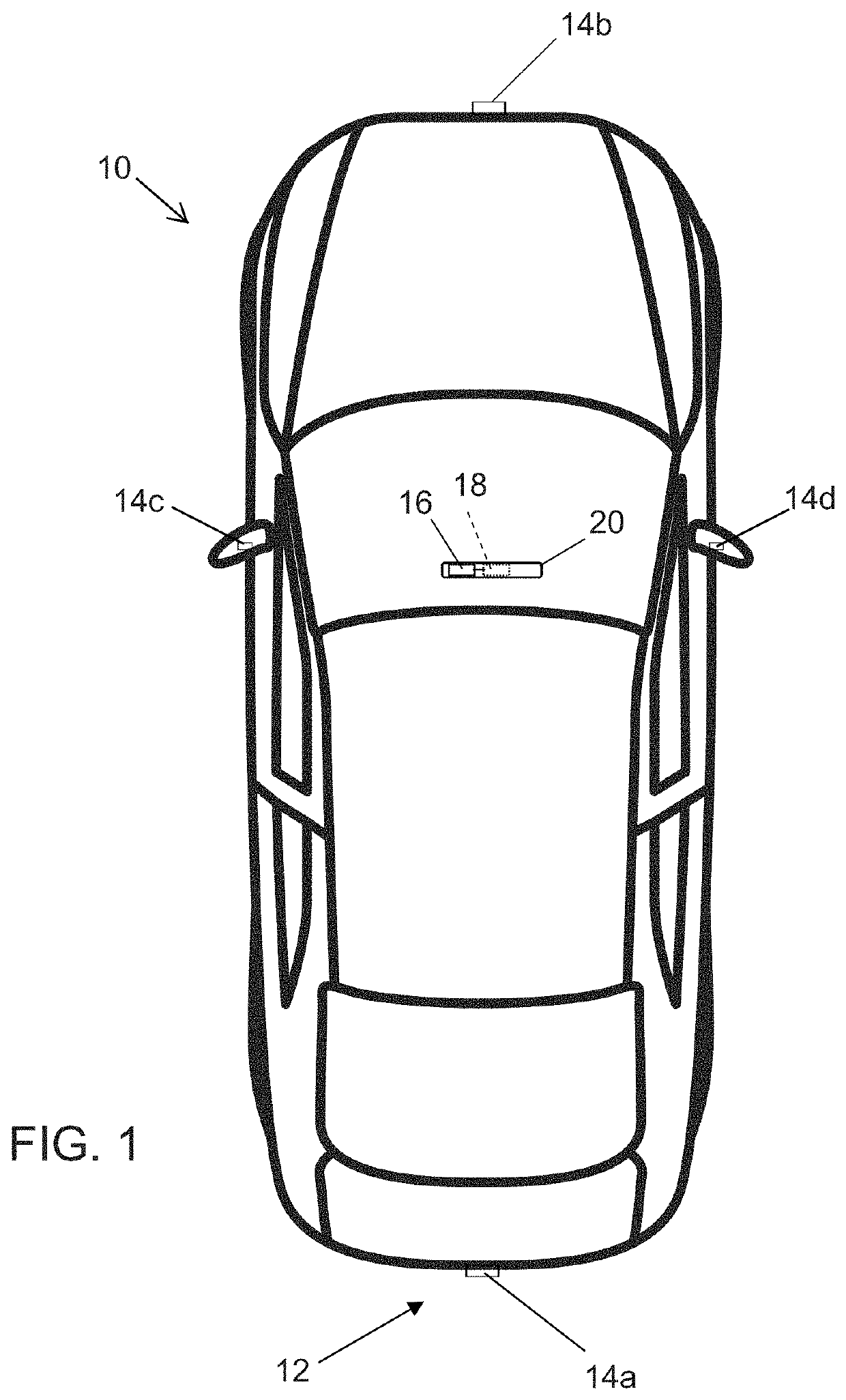
[0018]A vehicle vision system and / or driver assist system and / or object detection system and / or alert system operates to capture images exterior of the vehicle and may process the captured image data to display images and to detect objects at or near the vehicle and in the predicted path of the vehicle, such as to assist a driver of the vehicle in maneuvering the vehicle in a rearward direction. The vision system includes an image processor or image processing system that is operable to receive image data from one or more cameras and provide an output to a display device for displaying images representative of the captured image data. Optionally, the vision system may provide a top down or bird's eye or surround view display and may provide a displayed image that is representative of the subject vehicle, and optionally with the displayed image being customized to at least partially correspond to the actual subject vehicle.

[0019]Referring now to the drawings and the illustrative embo...


PUM


Abstract

A vision system of a vehicle includes at least one camera configured to be disposed at a vehicle so as to have a field of view exterior of the vehicle. Responsive to image processing of captured image data and with the at least one camera disposed at the vehicle, the image processor determines a three dimensional object present in the field of view of the camera and determines a point of interest on the determined object. The vision system uses triangulation to determine an estimated location in three dimensional space of the determined point of interest. The vision system processes additional frames of captured image data to enhance the estimation of the location in three dimensional space of the determined point of interest. The image processor is operable to estimate a distance to the determined object by comparing multiple frames of captured image data.

Description

CROSS REFERENCE TO RELATED APPLICATION[0001]The present application claims the filing benefits of U.S. provisional application Ser. No. 62 / 093,743, filed Dec. 18, 2014, which is hereby incorporated herein by reference in its entirety.FIELD OF THE INVENTION[0002]The present invention relates generally to a vehicle vision system for a vehicle and, more particularly, to a vehicle vision system that utilizes one or more cameras at a vehicle.BACKGROUND OF THE INVENTION[0003]Use of imaging sensors in vehicle imaging systems is common and known. Examples of such known systems are described in U.S. Pat. Nos. 5,949,331; 5,670,935 and / or 5,550,677, which are hereby incorporated herein by reference in their entireties.SUMMARY OF THE INVENTION[0004]The present invention provides a collision avoidance system or vision system or imaging system for a vehicle that utilizes one or more cameras (preferably one or more CMOS cameras) to capture image data representative of images exterior of the vehicl...

Claims


Application Information

Patent Timeline
Patent Type & Authority Patents(United States)
IPC IPC(8): G06K9/00G06T7/579
CPCG06K9/00805G06T7/579G06T2207/30261G06V20/58
Inventor GUPTA, NIKHILOKOUNEVA, GALINAZHANG, LIANG
Owner MAGNA ELECTRONICS INC
Why Eureka
Try Eureka