
Method and system for mitigating bowed rotor operation of gas turbine engine

a technology of gas turbine engine and rotor, which is applied in the direction of engine ignition, engine starter, liquid fuel engine, etc., can solve the problems of rotor assembly operating with undesirable magnitude, blade damage, or both, and achieve the effect of increasing fluid resistan

Active Publication Date: 2020-07-21
GENERAL ELECTRIC CO
View PDF24 Cites 3 Cited by
  • Summary
  • Abstract
  • Description
  • Claims
  • Application Information

AI Technical Summary

Benefits of technology

This approach allows for safe and efficient startup of gas turbine engines by reducing thermal gradients and eccentricity, minimizing vibrations and potential damage to the rotor and casing, even when rapid restart is required.

Problems solved by technology

Bowed rotor results in relatively large eccentricity relative to one or more casings surrounding the rotor assembly.
As such, when a rotor assembly resumes operation, such eccentricity may generally cause the rotor assembly to operate with undesirable magnitudes of vibrations such as to damage surrounding casings, bearing assemblies, load structures, etc.
Furthermore, such operation of the engine may result in airfoil blade tips rubbing into the surrounding casing, resulting in damage to the blades, the casings, or both.
However, in various instances, an engine may need to restart sooner than free convection heat transfer may allow.

Method used


Image

  • Method and system for mitigating bowed rotor operation of gas turbine engine
  • Method and system for mitigating bowed rotor operation of gas turbine engine
  • Method and system for mitigating bowed rotor operation of gas turbine engine

Examples


Embodiment Construction

[0026]Reference now will be made in detail to embodiments of the invention, one or more examples of which are illustrated in the drawings. Each example is provided by way of explanation of the invention, not limitation of the invention. In fact, it will be apparent to those skilled in the art that various modifications and variations can be made in the present invention without departing from the scope or spirit of the invention. For instance, features illustrated or described as part of one embodiment can be used with another embodiment to yield a still further embodiment. Thus, it is intended that the present invention covers such modifications and variations as come within the scope of the appended claims and their equivalents.

[0027]As used herein, the terms “first”, “second”, and “third” may be used interchangeably to distinguish one component from another and are not intended to signify location or importance of the individual components.

[0028]The terms “upstream” and “downstre...


PUM


Abstract

Embodiments of systems and methods for operating a gas turbine engine defining a bowed rotor condition are generally provided. The systems and methods include rotating a rotor assembly defining a bowed rotor condition from approximately zero revolutions per minute (RPM) to within a bowed rotor mitigation speed range, in which the bowed rotor mitigation speed range is defined by a lower speed limit greater than zero RPM and an upper speed limit less than or equal to an idle speed condition of the gas turbine engine; applying a load at the rotor assembly via an energy storage device; adjusting the load to limit rotational speed or acceleration of the rotor assembly to within the bowed rotor mitigation speed range for a period of time; and removing the load to enable rotation of the rotor assembly to the idle speed condition following the period of time.

Description

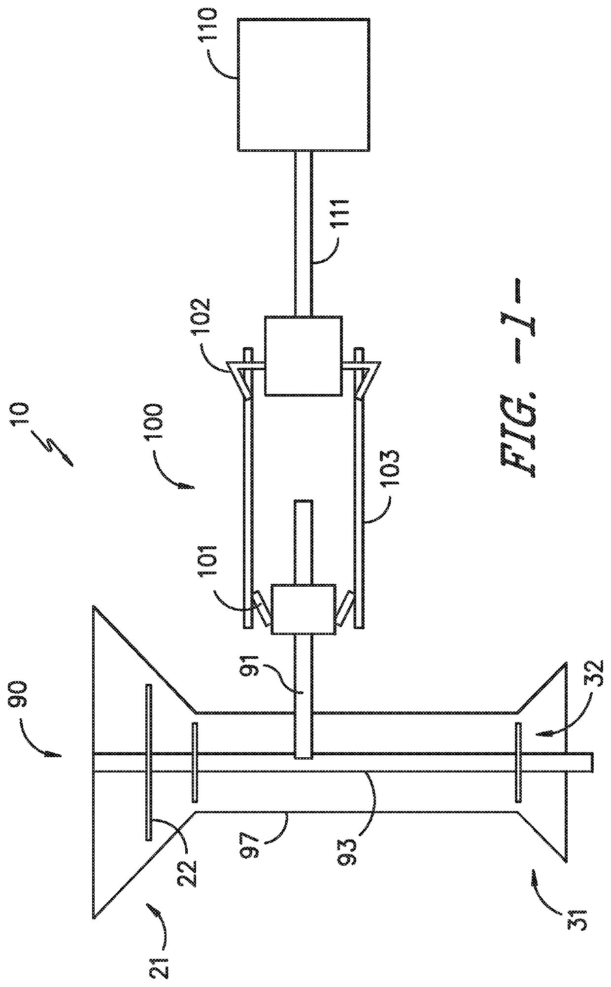
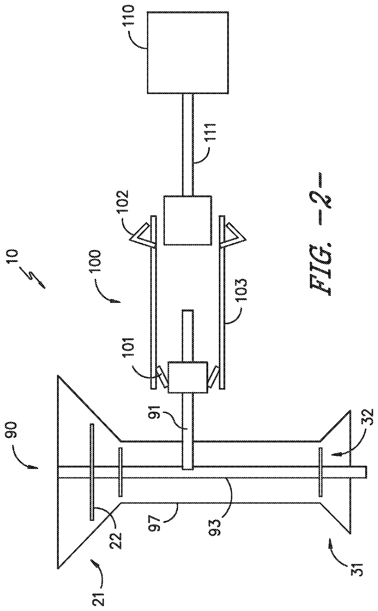
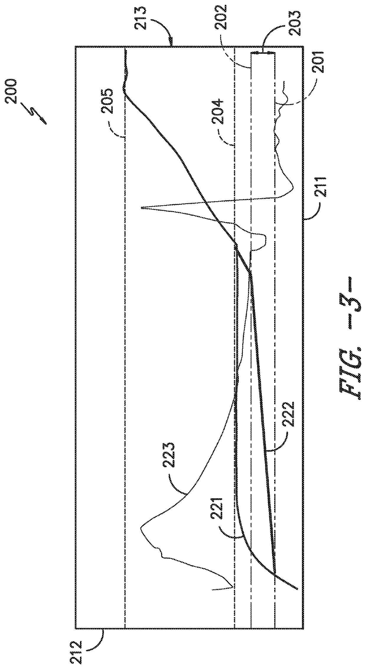
FIELD[0001]The present subject matter is directed generally to systems and methods for mitigating thermal bowing in gas turbine engines.BACKGROUND[0002]Gas turbine engines, such as those providing propulsion for aircraft, generate heat at the rotor assemblies during operation. Following shutdown of the engine, the rotor assembly is stationary (i.e., not rotating), which generally results in asymmetric heat distribution or thermal gradients circumferentially and / or axially along the rotor assembly. Such thermal gradients may generally result in thermal bowing or bowed rotor, such as along the radial, axial, and / or circumferential directions. Bowed rotor results in relatively large eccentricity relative to one or more casings surrounding the rotor assembly. As such, when a rotor assembly resumes operation, such eccentricity may generally cause the rotor assembly to operate with undesirable magnitudes of vibrations such as to damage surrounding casings, bearing assemblies, load structu...

Claims


Application Information

Patent Timeline
Patent Type & Authority Patents(United States)
IPC IPC(8): F01D19/02F04D29/66F01D25/34F16D43/04F02C7/26F01D5/02F01D19/00F02C7/268F04D29/52F16D43/30F02C7/277
CPCF01D19/02F04D29/668F01D25/34F05D2260/42F04D29/522F05D2260/85F02C7/26F01D5/02F02C7/277F05D2220/32F05D2270/304F05D2260/96F16D43/04F16D43/30F02C7/268F01D19/00F16D2043/145F16D43/14F01D21/006
Inventor ORKISZEWSKI, CHARLES STANLEY
Owner GENERAL ELECTRIC CO
Learn More