Product discharge control device for a form-fill-seal machine
a control device and form-filling machine technology, which is applied in the direction of packaging, packaged goods type, special packaging, etc., can solve the problems of limiting the maximum working speed of the device in practice, the limitation of the opening/closing speed of the blades of the discharge device, and the unsolved
- Summary
- Abstract
- Description
- Claims
- Application Information
AI Technical Summary
Benefits of technology
Problems solved by technology
Method used
Image
Examples
second embodiment
[0027]FIG. 4 is an elevational view of the driving means of the product discharge control device of the present invention ; and
third embodiment
[0028]FIG. 5 is an elevational view of the driving means of the product discharge control device of the present invention according to a
DESCRIPTION OF A PREFERRED EMBODIMENT
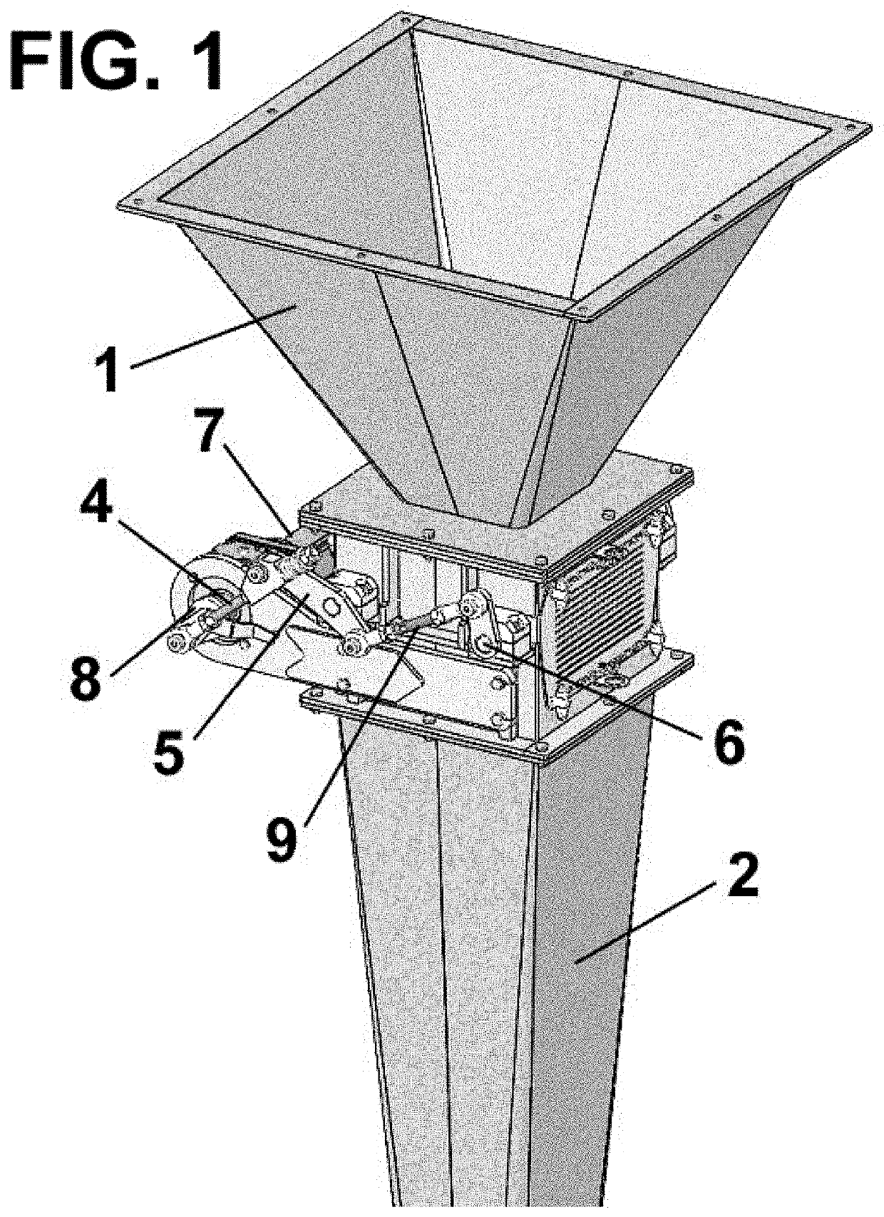
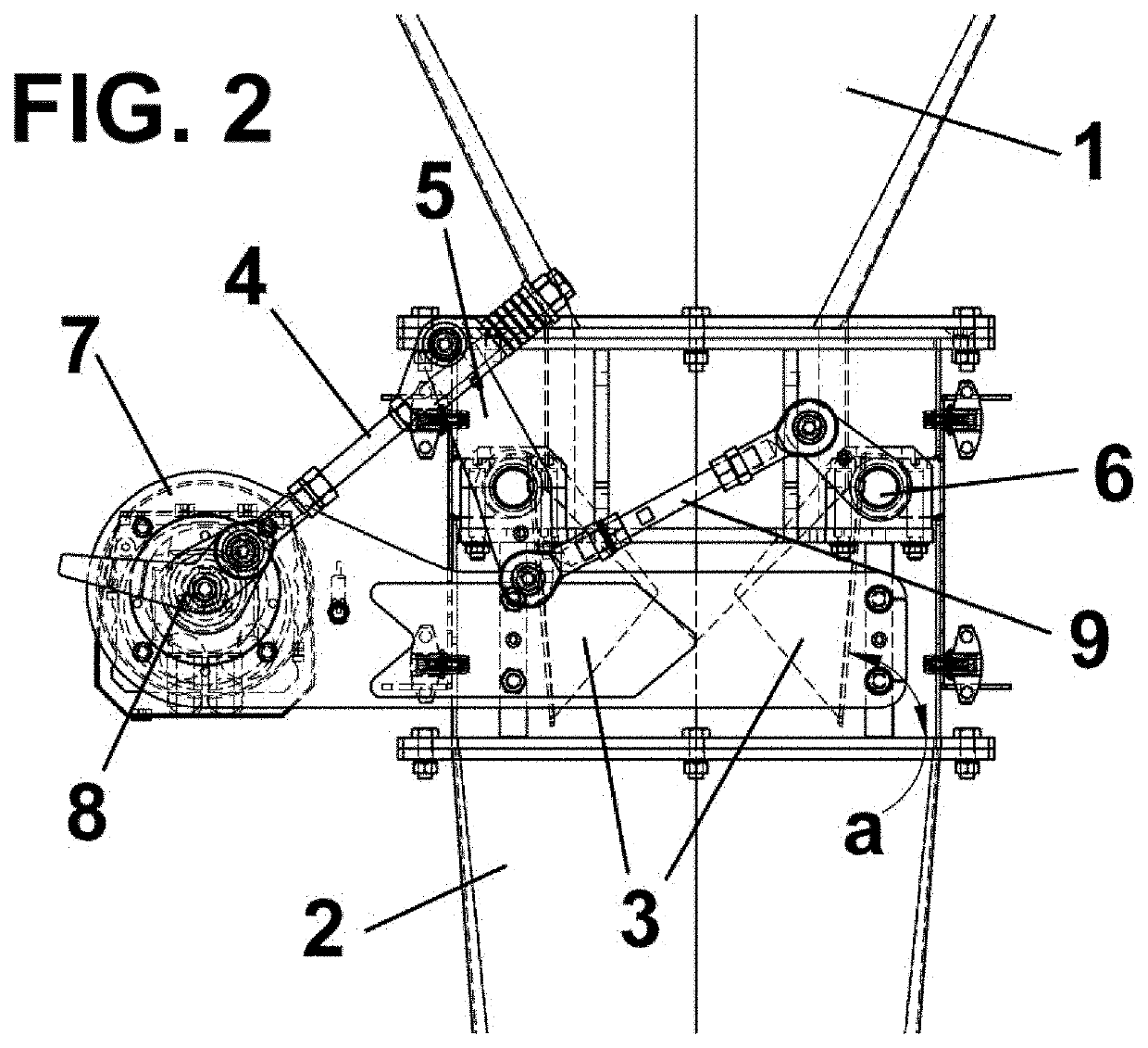
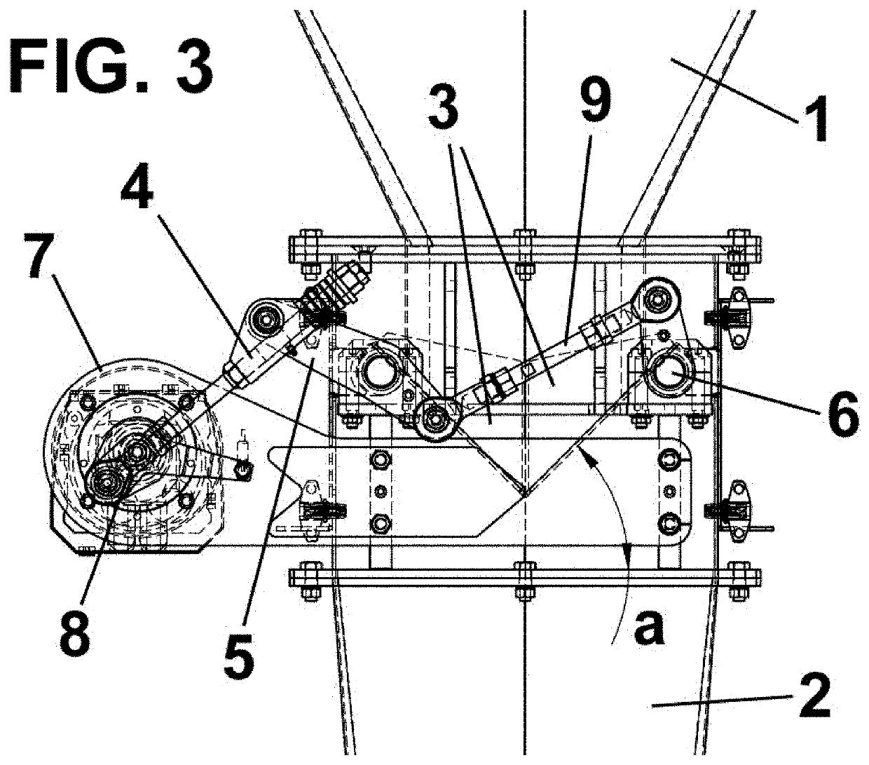
[0029]The drawings depict the product discharge control device according to the present invention, comprising a hopper 1 where the metered product amount used for filling the bag is discharged and a fill tube 2, connecting the discharge control device according to the present invention to the fill nozzle of the form-fill-seal machine.
[0030]The control device according to the present invention also comprises discharge control elements 3 that are movable between an open position in which product discharge is allowed, and a closed position in which product discharge is prevented, which allows receiving in this closed position a new metered product amount discharge released by the metering and weighing system located upstream.
[0031]Said discharge control elements 3 are arranged between the hopper 1 and the fill tube ...
first embodiment
[0048]For the sake of simplicity, the same reference numbers are used to indicate elements equivalent to the preceding embodiment. It should furthermore be indicated that only the driving means of the discharge control elements are different in this embodiment, the remaining elements being the same as in the
[0049]In this embodiment, the driving means of the discharge control elements also comprise first and second levers 5, 6 connected by means of said synchronizing connecting rod 9, each integral with a shaft for moving each of said discharge control elements 3, and the movement of which is driven by means of a drive belt 10 located between the output shaft of the motor 7, preferably a servomotor, and one of said levers 5, 6.
[0050]FIG. 5 shows a third embodiment of the discharge control device according to the present invention.
[0051]Like in the preceding case, for the sake of simplicity, the same reference numbers are used to indicate elements equivalent to the preceding embodimen...
PUM
| Property | Measurement | Unit |
|---|---|---|
| angle | aaaaa | aaaaa |
| angle | aaaaa | aaaaa |
| movement | aaaaa | aaaaa |
Abstract
Description
Claims
Application Information
 - R&D
- Intellectual Property
- Life Sciences
- Materials
- Tech Scout
- Unparalleled Data Quality
- Higher Quality Content
- 60% Fewer Hallucinations
Browse by: Latest US Patents, China's latest patents, Technical Efficacy Thesaurus, Application Domain, Technology Topic, Popular Technical Reports.
© 2025 PatSnap. All rights reserved.Legal|Privacy policy|Modern Slavery Act Transparency Statement|Sitemap|About US| Contact US: help@patsnap.com


