Renewable power system and sizing method for controllable plant associated with renewable power system

a renewable power system and renewable energy technology, applied in the direction of program control, greenhouse gas reduction, instruments, etc., can solve the problems of the overall operation of the electric grid, the problem of surely the prediction range, and the negative amount of energy, etc., to achieve the effect of small power and energy capacity of controllable plants and favorable total power output shap

Active Publication Date: 2020-08-04
NEC CORP
View PDF19 Cites 1 Cited by
  • Summary
  • Abstract
  • Description
  • Claims
  • Application Information

AI Technical Summary

Benefits of technology

[0015]By keeping the energy schedule within a certain range for a renewable power plant combined with controllable plant, it is possible to keep the needed power and energy capacity of controllable plant small and to guarantee favorable total power output shape.

Problems solved by technology

The volatile quality of produced power (energy) from renewable power plants creates problem for overall operation of the electric grid.
In combination with a load, however, the amount of energy can also be negative.
Some grid operation state and / or uncertainty in the prediction may make it necessary to keep the battery at a certain level.
In this exemplary embodiment, a problem is surely the prediction range (that is “k steps schedulable”).
Since the prediction range is translated into a delay in this scheme together with the basic integrator property of the battery (90 degrees phase lag), and it leads to instability.
However, the battery sizing method cross-checks with the available grid information (available reserve capacity) and estimates the feasibility and additional cost for the grid operation due to this measure.
As described above, the volatility of the power and energy production of the renewable plant and the associated controllable plant make it difficult to predict power and energy during a defined period for electric grid stability (supply / demand balance and so on).

Method used


Image

  • Renewable power system and sizing method for controllable plant associated with renewable power system
  • Renewable power system and sizing method for controllable plant associated with renewable power system
  • Renewable power system and sizing method for controllable plant associated with renewable power system

Examples


Embodiment Construction

[0032]The present inventors have noticed following problems.

[0033]Problem I: Battery size may be larger than needed in the above patent literatures. Scheduling control methods in the above patent literatures are not optimal when it comes to reducing battery size for the purpose of a “‘schedulable’ renewable power plant” comprising of renewable power plants and batteries considering prediction uncertainties.

[0034]Problem II: Power profile within one step size may be un-favorable as far as grid operation is concerned in the above patent literatures. If only flowchart based logic is used to control the power output of the battery (the controllable plant) in the renewable power plant system, the power profile may be unfavorable because of a lot of reasons, for example, the power output trajectory is too steep, jumps, or discontinuities.

[0035]Problem III: Power profile may not consider grid operation characteristics or grid operation state leading to a major stability and / or additional c...


PUM


Abstract

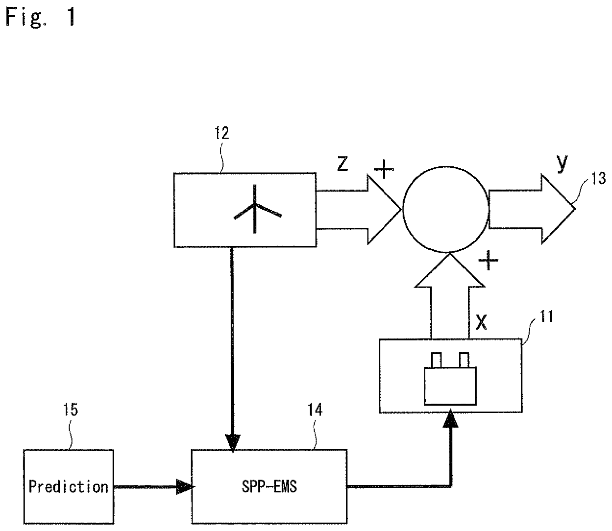
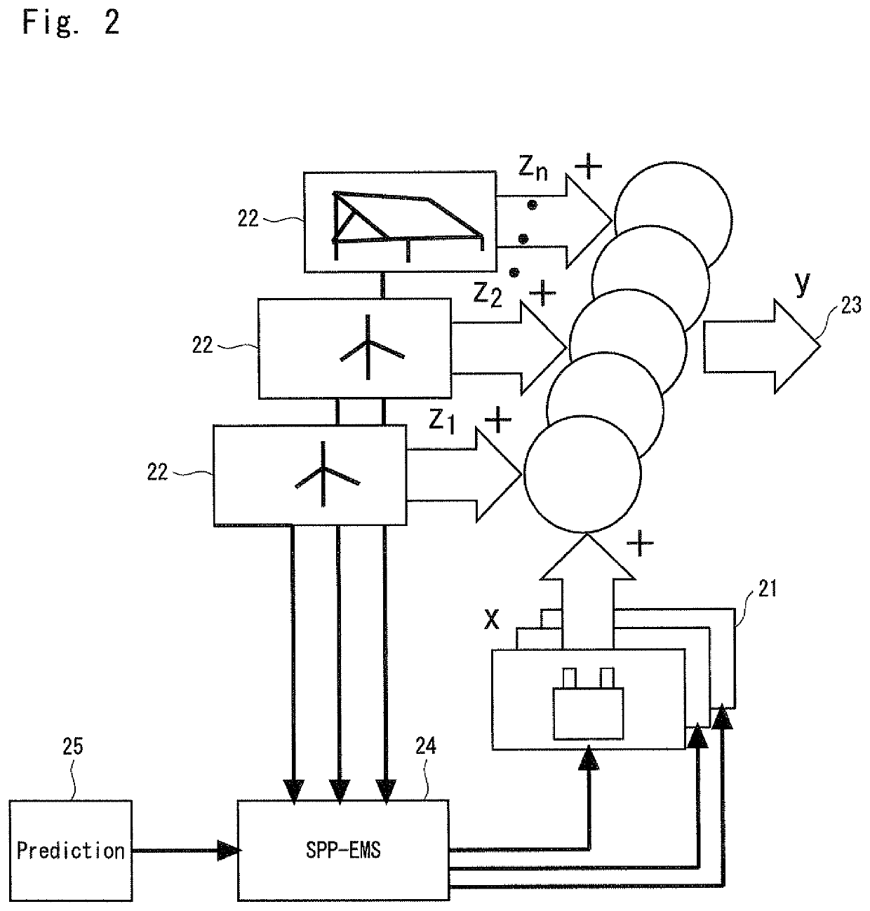
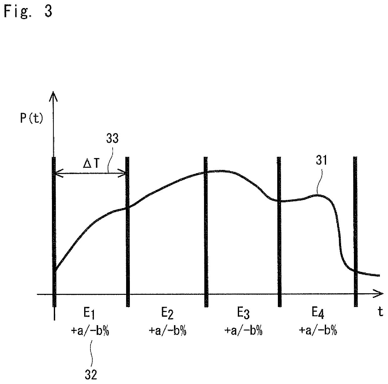
A renewable power system according to the exemplary embodiment includes a renewable power plant (121), a controllable plant (123) and an energy management system (128) which keeps an energy schedule within a certain tolerance in the next k (an integer greater than or equal to 1) steps by using a method that includes an optimization algorithm for a total power output shape within a step, and schedule changing algorithm for changing the energy schedule after the next k steps to keep a needed capacity of the plant regarding power and energy small. By keeping the energy schedule within a certain range for a renewable power plant combined with controllable plant, it is possible to keep the needed power and energy capacity of controllable plant small and to guarantee favorable total power output shape.

Description

[0001]This application is a National Stage Entry of PCT / JP2015 / 003432 filed on Jul. 8, 2015, the contents of all of which are incorporated herein by reference, in their entirety.TECHNICAL FIELD[0002]The present invention is related to a renewable power system and a sizing method for controllable plant associated with the renewable system.BACKGROUND ART[0003]Renewable energy resources have high volatility and therefore, they are difficult to predict and a predicted (calculated) schedule cannot be kept by the renewable power plant with desired accuracy.[0004]In future, more and more independent power producers (PPS—power producer and supplier company) will enter the traditional grid (in Japan and elsewhere). They will rely heavily on renewable power plants. Grid stability (supply / demand balance) will be an important issue. New market mechanism (or already existing market mechanism that have not yet been exploited) will play an important role.[0005]Patent literatures 1 to 5 disclose te...

Claims


Application Information

Patent Timeline
Patent Type & Authority Patents(United States)
IPC IPC(8): G05B19/042G06Q50/06H02J3/38H02J3/00H02J3/32
CPCH02J3/32G06Q50/06H02J3/00G05B19/042H02J3/38G05B2219/2639Y02E70/30H02J3/003H02J2300/20H02J3/381Y04S10/50H02J3/466
Inventor VIEHWEIDER, ALEXANDERKUDO, KOJI
Owner NEC CORP
Why Eureka
Try Eureka