Vehicle trim bar and fixing arrangement for a vehicle trim bar

a technology for vehicle trim and fixing arrangement, which is applied in the direction of superstructure, transportation and packaging, superstructure subunits, etc., can solve the problems of increasing the throughput time in production and assembly inaccuracy

Active Publication Date: 2020-08-11
MOTHERSON INNOVATIONS CO LTD
View PDF3 Cites 0 Cited by
  • Summary
  • Abstract
  • Description
  • Claims
  • Application Information

AI Technical Summary

Benefits of technology

[0012]The present invention is based on the idea to configure a trim bar with an additional web manufactured from plastic material, in particular heat-resistant plastic, which positions the trim bar in the desired position within the channel or above the bottom of the channel. At the same time, the support web functions as a stabilizer against pressure loads caused by the trim bar. The actual mounting of the trim bar is achieved only by means of the fixing leg, e.g. by means of a connection to a wall of the channel proximate to the opening of the channel, wherein the connection may be standardized, for example. The particular advantage of a web manufactured from plastic material is that such a web may be cut to size or shortened without great effort, depending on the dimensions of the channel, and is thus adjustable height. For example, the support web may be manufactured with excess length, e.g. a length of 35 mm, wherein channels having a depth between 10 mm and 30 mm may be provided. For a precise fitting of the trim bar, the support web may now simply be cut to a certain height for the desired configuration, i.e. for example 10 mm, 20 mm or 30 mm, e.g. by means of water jet cutting, laser cutting, punching or a similar appropriate process. Thus, a standard trim bar may be used for a large number of body shell structures and channel geometries i.e. dimensions. Additional clips and / or spacers are no longer required, therefore simplifying assembly in general and leaving less room for possible assembly faults. Last but not least, reduction in cycle times and manufacturing costs may be achieved.
[0014]According to one embodiment, the support web may be adapted to have a variable height. For example, the support web may be provided with markings, perforations or other cutting aids which make it particularly simple and fault-free for cutting the support web to the desired height. Generally, an advantageous plastic material may be used for the support web, which offers an ideal compromise between stability and simple detachability, such that the support web is sufficiently strong and stiff to support the vehicle trim bar on the one hand, and may be cut to length easily and efficiently using cost-effective processes on the other hand.
[0018]According to a further embodiment, the trim bar profile may be C-shaped. Each of the legs of the “C” shape may be adapted as a fixing leg, while the corresponding other leg functions as a support leg. A nearly C-shaped design of the trim bar profile is particularly simple to install. For this purpose, the vehicle trim bar may, for example, be slid in and / or inserted into the channel and fixed to the vehicle structure using the fixing leg, e.g. by means of fixing openings and / or mounting brackets, or the like, provided for this purpose. If the length of the support web has previously been adapted to the depth of the channel, e.g. by cutting to length, the vehicle trim bar is automatically sitting on the channel bottom, and covers the channel in an accurately fitting manner with the vehicle structure.
[0019]According to another embodiment, the trim bar profile may be adapted with a trim bar core and a trim bar coating. The trim bar core may be, at least partially, embedded in the trim bar coating. In particular, the trim bar core may be completely embedded in the trim bar coating. In alternative embodiments, however, the trim bar core may also only be partially coated. For example, a trim bar profile which is open on one side may be provided, in which the trim bar core on one side of the trim bar profile remains open towards the outside. In a preferred exemplary embodiment, the trim bar profile may have an open trim bar core on a visible area facing away from the vehicle. In another preferred exemplary embodiment, the trim bar profile may have an open trim bar core on an inner surface facing the vehicle opposite from the visible area. The trim bar coating may function as the structural core of the trim bar profile providing stability and strength. The trim bar coating, on the other hand, may be manufactured from a material that is as light as possible and yet resistant to wear and tear. In addition, the trim bar coating itself may be coated with a varnish, paint, protective layer, etc. to ensure temperature resistance, fluid repellency, and durability. In alternative embodiments, however, the trim bar profile may also consist entirely or substantially entirely of one material, e.g. a metal material, e.g. aluminum or a plastic material.
[0022]According to a further embodiment, the fixing leg may be adapted with at least one latching arm for, in particular, releasably fixing in at least one mounting bracket. According to this embodiment, the vehicle trim bar may be attached by simply inserting the latching arm into an opening or receptacle provided for this purpose, e.g. on at least one mounting bracket. The assembly according to this embodiment is therefore particularly fast and simple to implement. Alternatively or additionally, other positive-locking, friction-locking, and / or material-locking connection techniques may also be used in order to attach the vehicle trim bar by means of the fixing leg.
[0028]According to another embodiment, the vehicle trim bar may cover the channel in an accurately fitting manner. In addition, the channel may be sealed by sealing lips arranged on the vehicle trim bar.

Problems solved by technology

This not only increases the throughput time in production, but also causes possible assembly inaccuracies during installation to due to the complex structure.

Method used


Image

  • Vehicle trim bar and fixing arrangement for a vehicle trim bar

Examples


Embodiment Construction

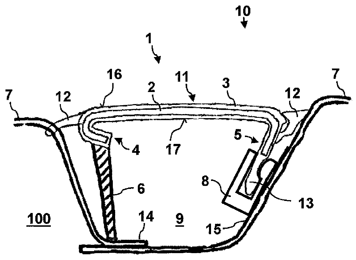
[0035]FIG. 1 shows a schematic cross-sectional view of a fixing arrangement 10 comprising a vehicle trim bar 1 according to an embodiment of the present invention.

[0036]In the fixing arrangement 10, a channel 9 in a vehicle structure 7 of a vehicle 100, e.g. a motor vehicle, is covered by a vehicle trim bar 1 in an accurately fitting manner. For example, channel 9 may be a roof gutter / drip rail, roof ditch and / or roof channel or the like formed in or on the roof of a motor vehicle. In this particular exemplary embodiment, the vehicle structure 7 is adapted as a roof structure, comprising a channel 9, for example, representing a roof channel between a roof panel and a side panel. In this example, the vehicle trim bar 1 thus functions as a roof trim bar or roof trim strip for covering the channel. However, in the present embodiment the roof trim bar is to be understood as an example only. In principle, the vehicle trim strips according to the present invention may be used for covering...


PUM


Abstract

The present invention relates to a vehicle trim bar, in particular a roof trim bar, for covering a channel, in particular a roof channel, in a vehicle structure having a trim bar profile which is formed with a fixing leg for fixing the vehicle trim bar within the channel to the vehicle structure and a support leg for supporting the vehicle trim bar on a channel bottom of the channel, the support leg being formed with a support web which projects from the trim bar profile in a manner extending along a longitudinal direction of the vehicle trim bar and which is manufactured from a plastic material. Furthermore, the invention relates to a fixing arrangement for a vehicle, in particular a motor vehicle, comprising such a vehicle trim bar.

Description

[0001]This application claims priority to German Application No. DE 102018201649.6, filed on Feb. 2, 2018. The entire contents of the above-mentioned patent applications are incorporated herein by reference as part of the disclosure of this U.S. application.FIELD OF INVENTION[0002]The present invention relates to a vehicle trim bar for covering a channel in a vehicle structure. The present invention further relates to a fixing arrangement for such a vehicle trim bar on a vehicle. Furthermore, the present invention relates to a vehicle comprising such a fixing arrangement. In particular, the present invention relates to a vehicle roof trim bar for covering a channel on a motor vehicle.BACKGROUND[0003]In automotive engineering, trim bars or strips are often used as trim parts for covering various recesses, ditches, gaps, channels, joints, or grooves in or on a vehicle body. For example, channel-shaped welding grooves between structural components of the vehicle body may be covered by ...

Claims


Application Information

Patent Timeline
Patent Type & Authority Patents(United States)
IPC IPC(8): B60R13/02B60R13/06B60R13/04
CPCB60R13/06B60R13/04B60R13/02B60R13/0206B60R2013/0287
Inventor WITTMANN, PETER
Owner MOTHERSON INNOVATIONS CO LTD
Why Eureka
Try Eureka