Jet burner

a burner and jet technology, applied in the field of burners, can solve the problems that the conventional burner cannot achieve the expected fuel burning efficiency, and achieve the effects of increasing the burning time of fuel, and increasing the fuel burning efficiency

Active Publication Date: 2020-09-01
PURE METHANOL ENERGY TECH CO LTD
View PDF8 Cites 0 Cited by
  • Summary
  • Abstract
  • Description
  • Claims
  • Application Information

AI Technical Summary

Benefits of technology

[0005]To achieve one of objectives mentioned in the present disclosure, the present disclosure provides a jet burner capable of sufficiently increasing the fuel burning efficiency.
[0007]Accordingly, under the reaction of the jet pipe, the jet burner of the present disclosure can increase the burning stay time of the fuel in the interior of the burning chamber, so as to achieve the objective of increasing the fuel burning efficiency.
[0022]Mainly under the reaction of the jet pipe, the jet burner provided by the present disclosure can increase the burning time of the fuel in the interior of the burning chamber to achieve the objective of increasing the fuel burning efficiency. Further by using the effect which the high-pressure gas supplying unit accelerates the fuel which incomes the nozzle, the atomization effect of the fuel which has passed the nozzle is increased, and simultaneously, the gas fluid flux is provided to the interior burning chamber to increase the fuel burning efficiency. Even, under the reaction of the wind speed auxiliary unit, the flowing speed and flowing flux of the accelerated gas fluid are increased, such that the relatively positive and reliable means for increasing the fuel burning efficiency and the performance are provided, and the effect of the high temperature on the relative units can be prevented. Furthermore, by using the jet burner, not only the pollutant generated by burning the diesel and the heavy oil can be reduced, but also it eases the alcohol to be the fuel, such that the jet burner can be used in the room environment of the restaurant, organization or school.

Problems solved by technology

Though the conventional burner utilizes the air blower to generate the accelerating gas fluid, in the actual application, the fuel injected into the burning chamber may be blew out from the burning chamber in the non-complete burning status due to the over-reaction of the accelerating gas fluid, such that the conventional burner cannot have the expected fuel burning efficiency.

Method used


Image

  • Jet burner
  • Jet burner
  • Jet burner

Examples


Embodiment Construction

[0033]To understand the technical features, content and advantages of the present disclosure and its efficacy, the present disclosure will be described in detail with reference to the accompanying drawings. The drawings are for illustrative and auxiliary purposes only and may not necessarily be the true scale and precise configuration of the present disclosure. Therefore, the scope of the present disclosure should not be limited to the scale and configuration of the attached drawings.

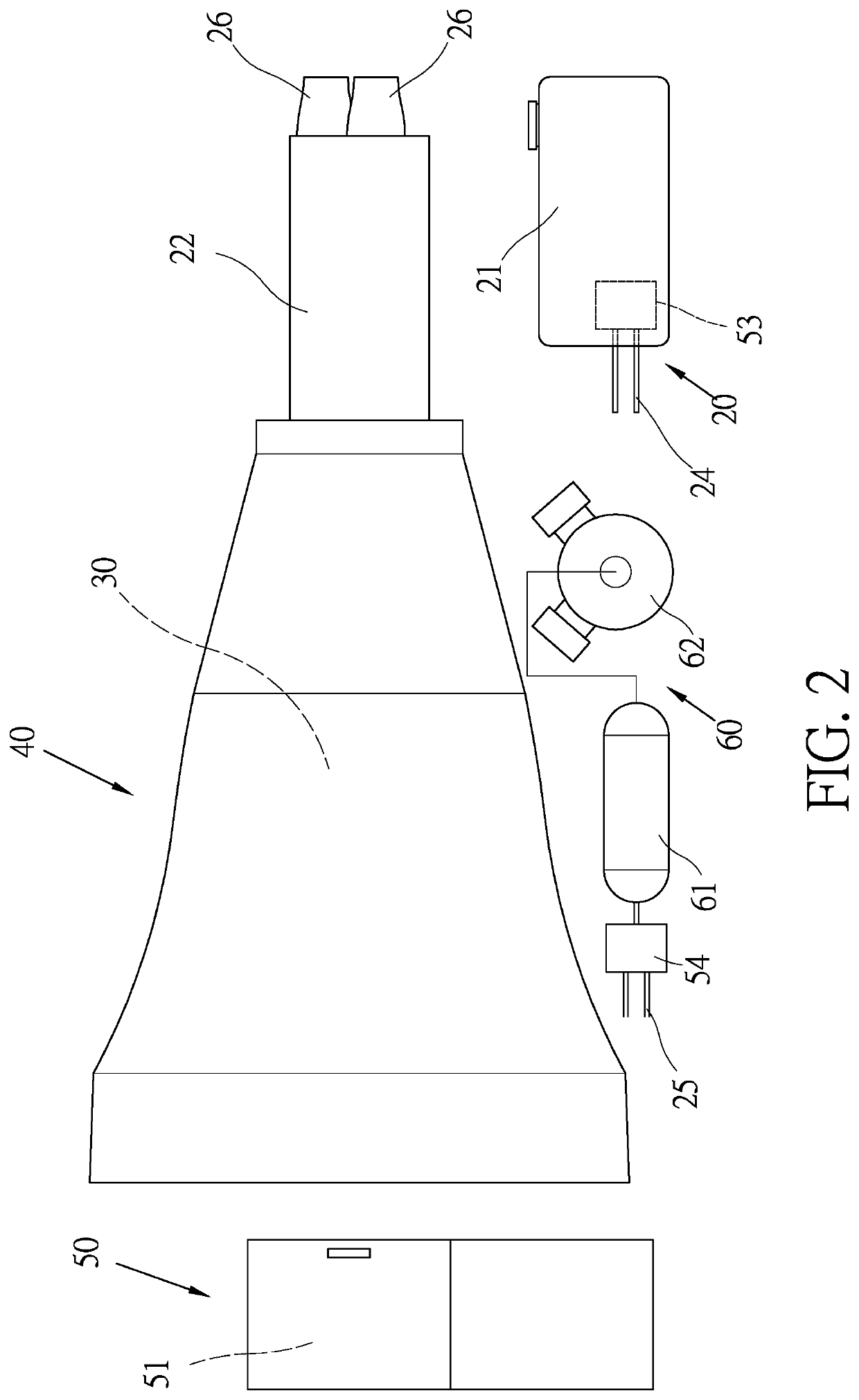
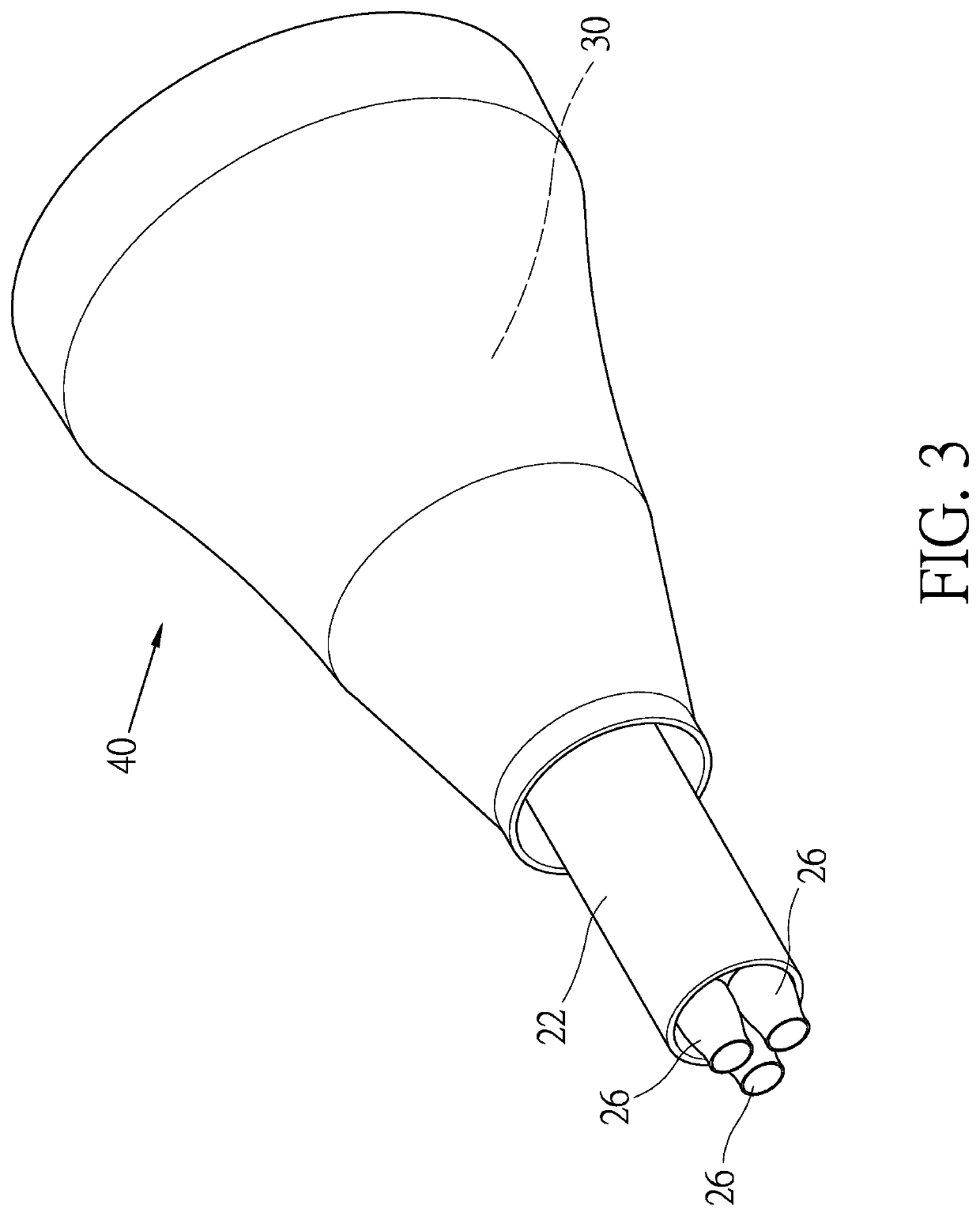
[0034]The present disclosure mainly provides a jet burner for sufficiently increasing the fuel burning efficiency, the jet burner of the present disclosure basically comprises a burner unit 20 and an air blower 30 as shown in FIG. 2 through FIG. 5, and the details are illustrated as follows.

[0035]The burner unit 20 is installed with a fuel bucket 21 for storing fuel and a burning chamber 22 having a tubular shape, wherein interior of the burning chamber 22 is installed with at least one nozzle 23, at le...


PUM


Abstract

A jet burner of the present disclosure basically includes a burner unit and an air blower disposed at a rear end of a burning chamber of the burner unit, wherein the burner unit is installed with a fuel bucket for storing fuel and the burning chamber having a tubular shape. Interior of the burning chamber is installed with a least one nozzle, at least one fuel pipe coupled to the fuel bucket is installed at each the nozzle, a front end of the burning chamber is installed with at least one jet pipe, and a pipe diameter of each the jet pipe is less than an inner diameter of the burning chamber. Under the reaction of the jet pipe, the burning stay time of the fuel in the interior of the burning chamber is increased, as to achieve the objective of increasing the fuel burning efficiency.

Description

BACKGROUND1. Technical Field[0001]The present disclosure relates to a burner, in particular to, a jet burner for sufficiently increasing the fuel burning efficiency.2. Description of Related Art[0002]According to prior art, the burner is widely used in a boiler, a heating furnace, a drying equipment and an industrial furnace and other thermal machinery, and the basic architecture of the conventional burner is shown as FIG. 1. The conventional burner is installed with a burning chamber 12 coupled to an air blower 11, and interior of the burning chamber 12 is installed with a plurality of nozzles 13 coupled to a fuel providing device (not shown in the drawings). Mainly, the air blower 11 generates the accelerating gas fluid in the burning chamber 12, and after the fuel injected into the burning chamber 12 is fired, accompanying the gas fluid in the burning chamber 12, the fire can be spurted and burned at the front end of the burning chamber 12.[0003]The fuel of the conventional burne...

Claims


Application Information

Patent Timeline
Patent Type & Authority Patents(United States)
IPC IPC(8): F23D14/22F23D14/64F23D14/34F23D11/26F23D11/38F23D11/40
CPCF23D14/22F23D11/38F23D11/404F23D14/64F23D11/26F23D11/406F23D14/34F23D2207/00F23D11/10F23D11/24F23D11/36F23D11/40
Inventor CHANG, TENG-YUN
Owner PURE METHANOL ENERGY TECH CO LTD
Why Eureka
Try Eureka