
Device and method for determining an axial twist position of an electrode array for electrical impedance tomography

a technology of electrical impedance tomography and electrode array, which is applied in the field of electric impedance tomography, can solve the problems of not being able to accurately determine the position of the electrode array, bringing about differences in impedances, and not being able to measure or acquire and input a plurality of patient data in many application situations,

Active Publication Date: 2020-09-08
DRAGERWERK AG
View PDF6 Cites 0 Cited by
  • Summary
  • Abstract
  • Description
  • Claims
  • Application Information

AI Technical Summary

Benefits of technology

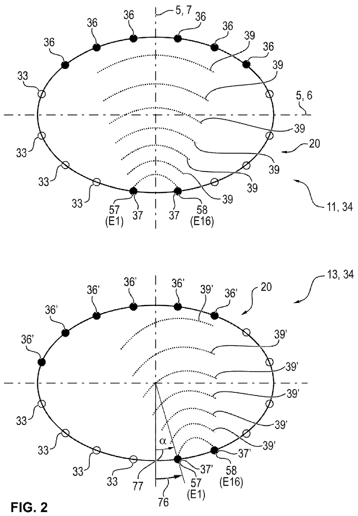
[0020]Knowing the above-described drawbacks of the known prior art, an object of the present invention is to provide an electrical impedance tomography (EIT) device suitable for imaging of the lungs with an electrode array, which is associated with the electrical impedance tomography device and which makes it possible to determine an axial twist angle / circumferential shift / twist angle (axial twist / axial torsional offset) of the electrode array or an axial torsion α of the electrode array.
[0022]Another object of the present invention is to provide a method for the operation of an electrical impedance tomography (EIT) device suitable for imaging of the lung, which makes it possible to determine an axial twist angle of the electrode array or an axial torsion α of the electrode array.
[0059]In a preferred embodiment of the electrical impedance tomography device, the calculation and control unit is configured to calculate impedance values and / or impedance changes or impedance distributions in the thorax in the plane of the electrodes on the thorax on the basis of the plurality of measured values provided by the signal acquisition unit by means of an image reconstruction algorithm and to determine a tidal image on the basis of the calculated impedance values and / or impedance changes and / or impedance distributions in the thorax in the plane of the electrodes on the thorax and on the basis of the determined axial twist angle and / or torsion angle α and to incorporate same into the control signal and to provide the control signal for the output unit. This makes it possible to eliminate the determined axial twist angle and / or the torsion angle α due to adaptation or shifting of indexes during the addressing of indexed vectors, indexed data fields or indexed matrices in the EIT measuring channels with related impedance values in case of the image reconstruction for preparing the tidal image from the EIT measuring channels.
[0062]The calculation and control unit may be configured as a central unit in the electrical impedance tomography device, which coordinates both the acquisition and analysis of the measured signals and initiates the determination and the provision of the control signal as well as the consideration of the control signal during the output of the corrected tidal image. A configuration of the calculation and control unit, in which a plurality of distributed units for acquisition, analysis and determination and provision of the control signal interact, for example, in the manner of the so-called cloud computer, instead of a central unit, may also be advantageous, however. A possible advantage from this may be achieved such that the correction of the tidal image and the provision thereof may take place at a location different from the location, at which measured signals are acquired.

Problems solved by technology

Moreover, a comparatively reproducible and representative horizontal position of the electrode belt during application can be achieved due to an orientation at the costal arches, so that possible errors in the horizontal attachment of the electrode belt to the thorax occur rather rarely.
In this case, however, at least the elements of the skeleton or of the organs still bring about differences in the impedances between the feeding electrodes and the measuring electrodes located opposite them.
For the operation of electrical impedance tomography systems, it is not really advantageous in many application situations to have to measure or acquire and input a plurality of patient data before the beginning of the application.
It is not possible to determine a horizontal position of the belt, as well as especially not an axial torsion or shifting about the vertical axis of the body (longitudinal or sagittal or front plane of the body), even by inputting biometric data of the patient.

Method used


Image

  • Device and method for determining an axial twist position of an electrode array for electrical impedance tomography
  • Device and method for determining an axial twist position of an electrode array for electrical impedance tomography
  • Device and method for determining an axial twist position of an electrode array for electrical impedance tomography

Examples


Embodiment Construction

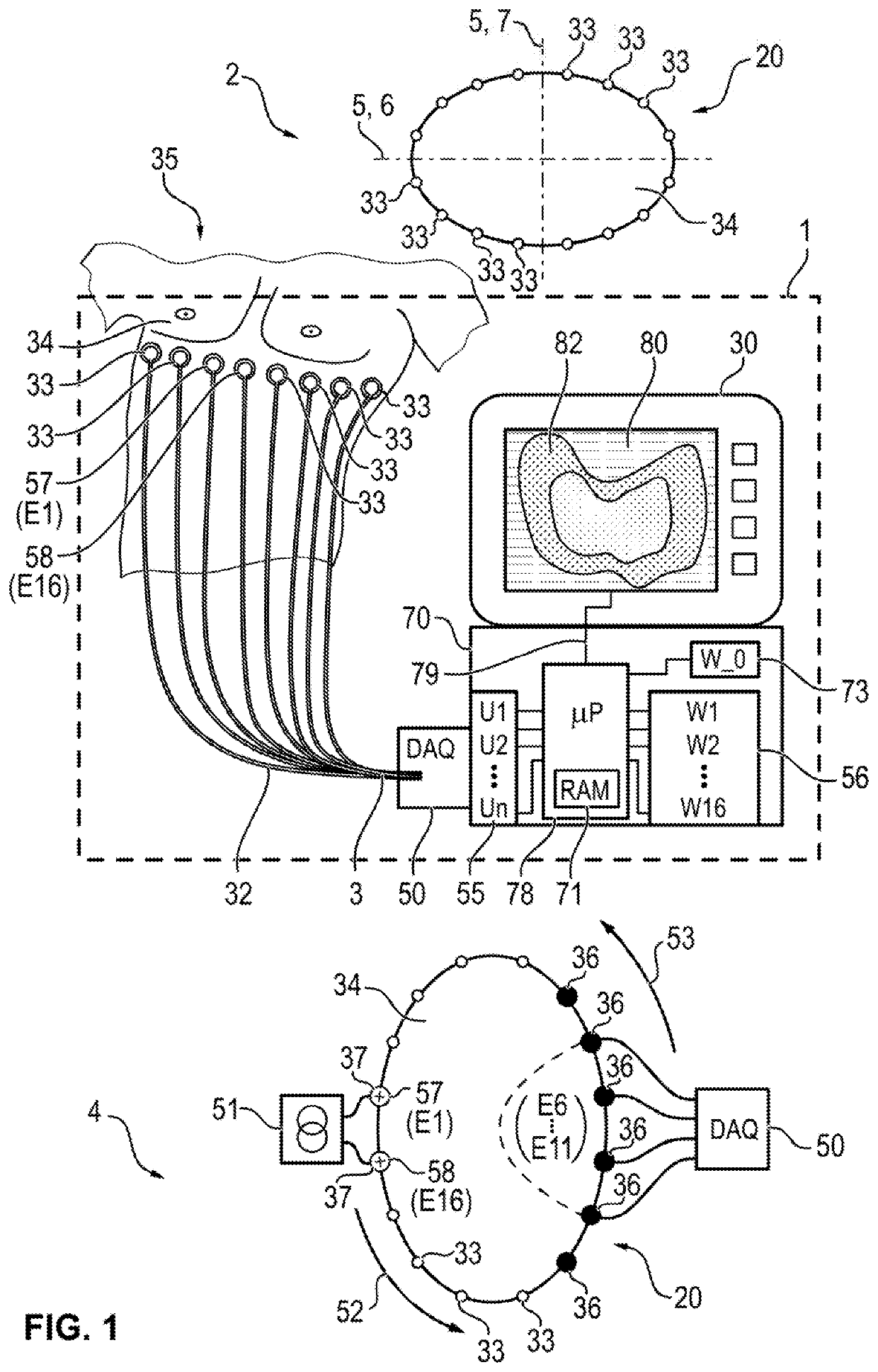
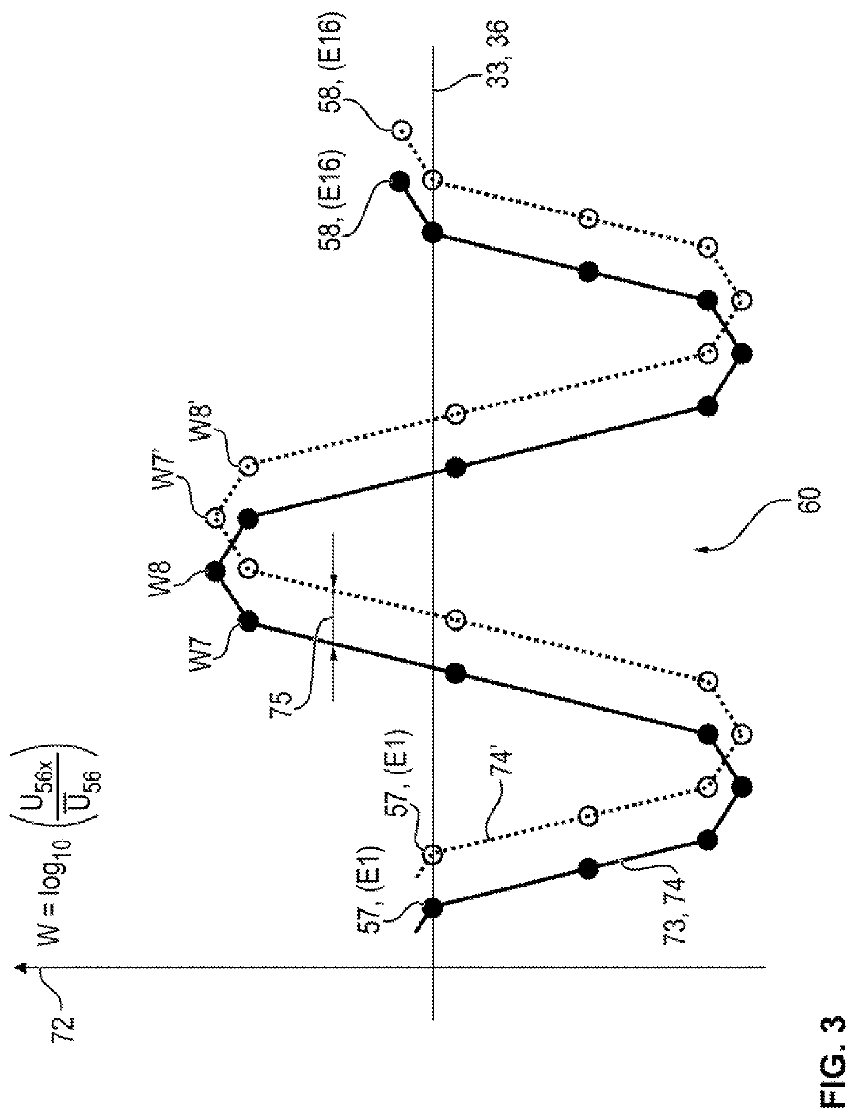
[0085]Referring to the drawings, FIG. 1 shows an impedance tomography device 1. A number of electrodes 33 is arranged on the thorax 34 of a patient 35 in the impedance tomography device. EIT data 3 are transmitted from the electrodes 33 to a calculation and control unit 70 by means of a data acquisition unit 50. The EIT data 3 are transmitted from the electrodes 33 by means of wired connections 32. A processor unit 78 and a memory 71 are arranged in the calculation and control unit 70. The processor unit 78 processes the EIT data 3, which are provided by the signal acquisition unit 50. It is shown in this FIG. 1 that the EIT data 3 reach the calculation and control unit 70 with the processor unit 78 as measured signals 55. The processor unit 78 determines a current signal trace (W1 . . . W16) 60 from selected measured signals (U56X) 56 by means of suitable calculation methods and algorithms from the measured signals 55. Selected measured signals (UX56) 56 are in this connection thos...


PUM


Abstract

An electrical impedance tomography device (1) includes an electrode array, including a plurality of electrodes (33) arranged spaced apart from one another, a signal feed unit (51) and a signal acquisition unit (50). A calculation and control unit (70) is configured to determine a situation with an axial twist angle of the electrode array on a thorax (34) of a human being and to provide a control signal (79), which indicates the situation with axial twist angle of the electrode array. The calculation and control unit (70) may be configured as a central unit or an array of distributed units (cloud computing) in order to determine and to provide the axial twist angle.

Description

CROSS REFERENCE TO RELATED APPLICATIONS[0001]This application claims the benefit of priority under 35 U.S.C. § 119 of German Application 10 2016 014 251.0, filed Nov. 30, 2016, the entire contents of which are incorporated herein by reference.FIELD OF THE INVENTION[0002]The present invention pertains to an electrical impedance tomography device with determination of the axial twist angle of an electrode array associated with the electrical impedance tomography device.[0003]The present invention further pertains to a method for the operation of an electrical impedance tomography device with determination of the axial twist angle of an electrode array associated with the electrical impedance tomography device.BACKGROUND OF THE INVENTION[0004]Electrical impedance tomography (EIT) devices are known from the state of the art. These devices are configured and intended to generate signals obtained by electrical impedance measurements and data and data streams obtained therefrom, an image, ...

Claims


Application Information

Patent Timeline
Patent Type & Authority Patents(United States)
IPC IPC(8): A61B5/05A61B5/00A61B5/053
CPCA61B5/7225A61B5/0536A61B5/6823A61B5/6844A61B5/7221A61B2562/043A61B2560/0475A61B5/053A61B5/0809A61B5/72
Inventor GÄRBER, YVO
Owner DRAGERWERK AG
Learn More